Composite drag-free mode realization apparatus for high-precision autonomous navigation, and method thereof

An autonomous navigation and drag-free technology, applied in the field of drag-free satellite systems, can solve problems such as light pressure interference, and achieve the effects of reduced interference, small relative position error, and high precision

Active Publication Date: 2018-10-12
ACAD OF OPTO ELECTRONICS CHINESE ACAD OF SCI
View PDF9 Cites 0 Cited by
  • Summary
  • Abstract
  • Description
  • Claims
  • Application Information

AI Technical Summary

Problems solved by technology

However, active lighting will cause light pressure interference to the inspection quality, and it is necessary

Method used


Image

  • Composite drag-free mode realization apparatus for high-precision autonomous navigation, and method thereof
  • Composite drag-free mode realization apparatus for high-precision autonomous navigation, and method thereof
  • Composite drag-free mode realization apparatus for high-precision autonomous navigation, and method thereof

Examples


Embodiment Construction

[0041] The present invention will be described in detail below with reference to the accompanying drawings and examples.

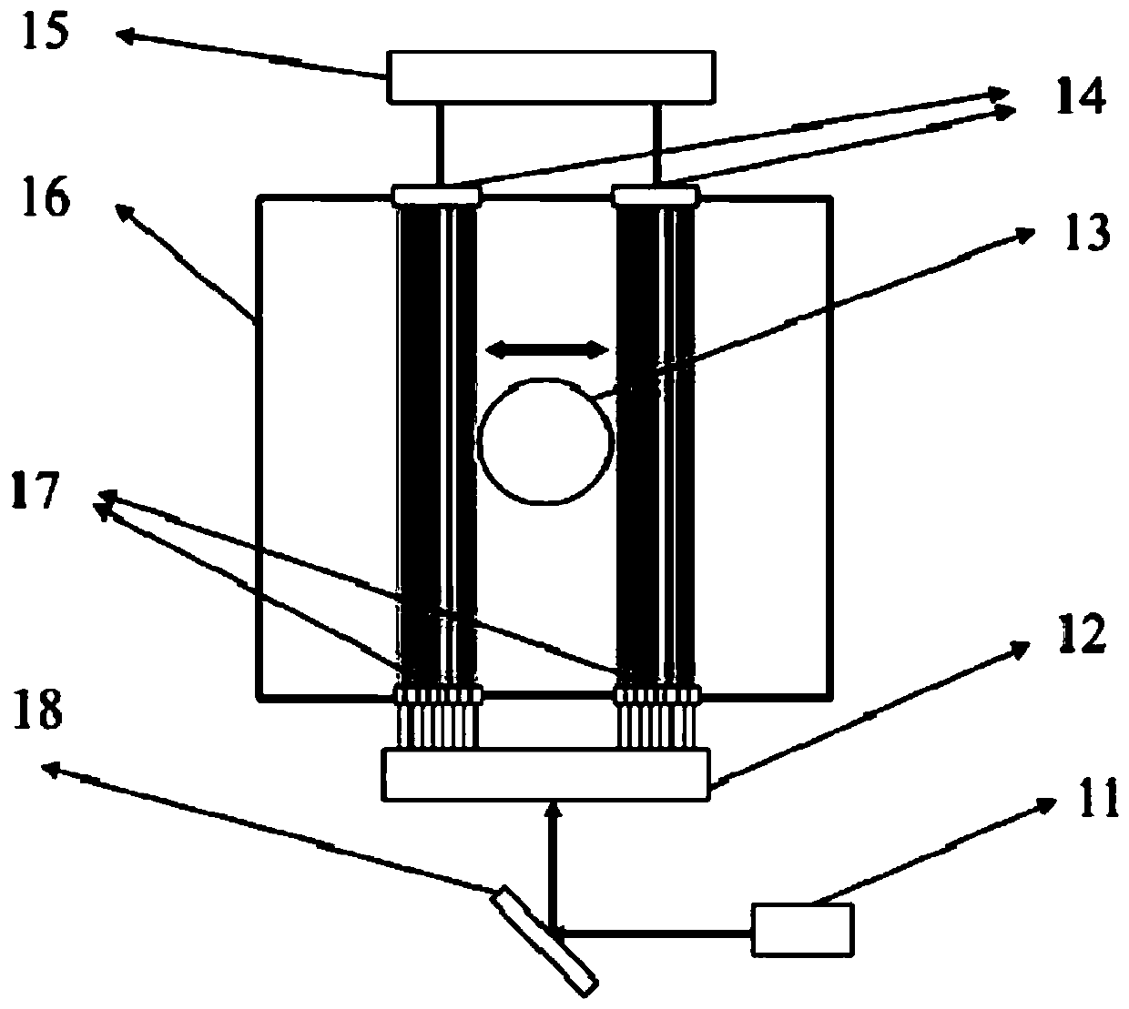
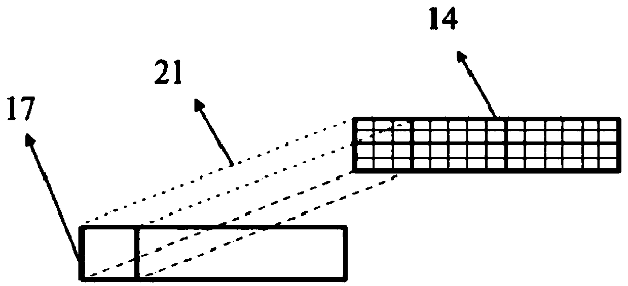
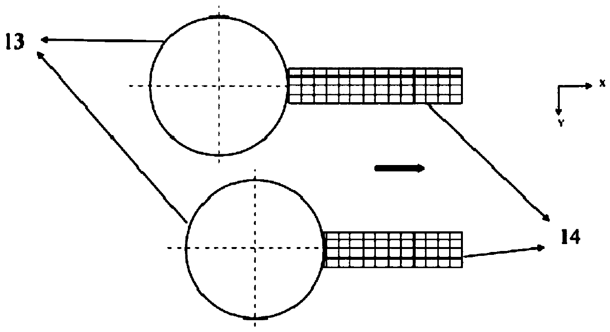
[0042] The present invention provides a compound drag-free mode realization device for high-precision autonomous navigation, including a laser array 11, a laser beam shaping device 12, a proof mass 13, a photoelectric conversion array 14, a data processing module 15, and a spacecraft cavity 16 , shaping laser input window 17 and mirror 18, such as figure 1 shown.

[0043] The laser array 11 is composed of N lasers, where N is an even number and N is not less than 2. In this embodiment, the laser is a 1064nm single-frequency laser, which can provide laser with stable power and frequency. The laser light intensity follows a Gaussian distribution, and the output power is on the order of milliwatts.

[0044] The reflector 18 sends the N beams of laser light output by the laser array 11 to the laser beam shaping device 12 after adjusting the optical path.

...


PUM


Abstract

The invention provides a composite drag-free mode realization apparatus for high-precision autonomous navigation, and a method thereof. The apparatus comprises a laser array, a laser beam shaping device, an examination mass block, a photoelectric conversion array, a data processing module, a spacecraft cavity and an input window. The laser beam shaping device divides beams emitted by lasers into aleft part and a right part, shapes the left part and the right part of the beams to obtain a rectangular beam, and distributes the rectangular beam to the input window; the rectangular beam enters the spacecraft cavity from a left input window and a right input window respectively, and is detected by the photoelectric conversion array; the photoelectric conversion array converts a detected optical signal into an electrical signal, and outputs the power of the electric signal to the data processing module; and the data processing module resolves the relative position and the relative acceleration of the examination mass block according to the relationship between of a power difference at two different moments and the relative position of the examination mass block. The apparatus and the method, which adopt a pure optical measuring way, can simultaneously measure the relative displacement and the non-conservative force acceleration, and improve the interference suppression of the examination quality.

Description

technical field [0001] The invention relates to the technical field of drag-free satellite systems, in particular to a device and method for realizing a compound drag-free mode for high-precision autonomous navigation. Background technique [0002] The tow-free satellite is mainly composed of the inspection mass and the satellite body. The inspection mass is located inside the satellite cavity. The satellite cavity is equivalent to a barrier, which can shield external environmental interference. Therefore, ideally, the inspection mass is only affected by gravity, and its orbit is a purely gravitational orbit. However, due to the disturbance of the external environment, the satellite body will have a relative displacement with the inspection mass. The satellite uses the thrust generated by the thruster to make itself follow the inspection mass block, that is, the center of mass of the satellite and the center of mass of the inspection mass always coincide, so the satellite bo...

Claims


Application Information

Patent Timeline
IPC IPC(8): G01C21/20G01C21/24
CPCG01C21/20G01C21/24Y02T90/00
Inventor 傅江良甘庆波
Owner ACAD OF OPTO ELECTRONICS CHINESE ACAD OF SCI
Why Eureka
Try Eureka