
Broadband multichannel channelization system and method based on optical frequency shift

A technology of optical frequency shifting and channelization, which is applied in the field of broadband multi-channel channelization systems, can solve the problems of poor out-of-band suppression ability of optical filtering and complex implementation of high-quality coherent optical combs, so as to avoid poor suppression ability and implementation Complicate, achieve simple effects

Active Publication Date: 2018-10-12
XIAN INSTITUE OF SPACE RADIO TECH
View PDF10 Cites 24 Cited by
  • Summary
  • Abstract
  • Description
  • Claims
  • Application Information

AI Technical Summary

Problems solved by technology

[0004] The problem solved by the technology of the present invention is: aiming at the technical difficulties of narrow-band optical filter and dual coherent optical comb generation in the current wideband signal channelization reception frequency conversion, a broadband multi-channel channelization method based on optical frequency shift is provided to realize broadband The channel division of microwave signals and the same intermediate frequency frequency conversion with high image rejection not only avoid the disadvantages of poor out-of-band suppression of optical filtering faced by traditional channelized reception, but also avoid the realization of high-quality coherent optical combs in channelized reception based on optical frequency combs Complicated Disadvantages

Method used


Image

  • Broadband multichannel channelization system and method based on optical frequency shift
  • Broadband multichannel channelization system and method based on optical frequency shift
  • Broadband multichannel channelization system and method based on optical frequency shift

Examples


specific Embodiment approach 1

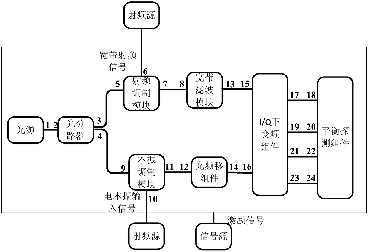
[0065] The first embodiment is a broadband multi-channel channelization system based on optical frequency shift, such as figure 1As shown, it consists of a light source, an optical splitter, a radio frequency modulation module, a local oscillator modulation module, a broadband filter module, an optical frequency shift component, an I / Q down-conversion component and a balance detection component. Wherein, the optical frequency shifting component is composed of three DPMZMs arranged in parallel, and each DPMZM includes an uplink MZM, a downlink MZM, and a main modulator; the uplink MZM and the downlink MZM of the DPMZM realize the electro-optic modulation of the excitation electrical signal, and the The main modulator of the DPMZM controls the optical signal output by the uplink MZM to be added or subtracted from the optical signal output by the downlink MZM, and then output from the DPMZM optical output port; The radio frequency signal and the electrical local oscillator input ...

specific Embodiment approach 2

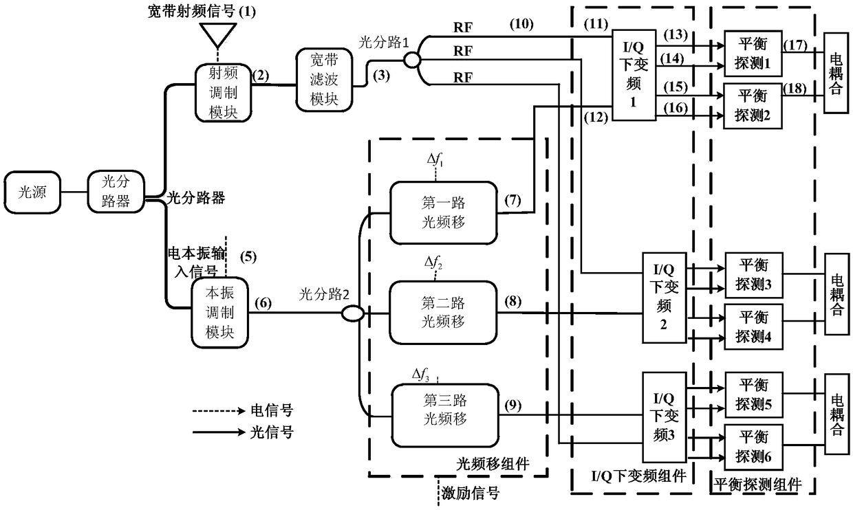
[0067] The second specific embodiment is radio frequency modulation, local oscillator modulation, broadband filtering and optical frequency shift, such as figure 2 shown. The system includes light source, optical splitter, radio frequency modulation module, local oscillator modulation module, broadband filter module, optical branch 1, optical branch 2 and optical frequency shifting components. The optical frequency shifting component includes a first optical frequency shift, a second optical frequency shift and a third optical frequency shift. The specific steps are:

[0068] Step 1: According to figure 2 , the continuous optical signal output by the light source is divided into two paths by the optical splitter and sent to the optical input end of radio frequency modulation and local oscillator modulation, the broadband radio frequency signal output by the radio frequency source is loaded to the radio frequency modulation, and the electric local oscillator input signal ou...

specific Embodiment approach 3

[0081] DETAILED DESCRIPTION OF THE PREFERRED EMBODIMENT Generation of three multiple channels with the same intermediate frequency signal. Such as figure 2 shown. The system includes two parts: I / Q down-conversion component and balanced detection component. The I / Q down-conversion components include I / Q down-conversion 1, I / Q down-conversion 2, and I / Q down-conversion 3, and the balance detection components include balance detection 1, balance detection 2, balance detection 3, balance detection 4, balance Probe 5 and Balance Probe 6. Methods as below:

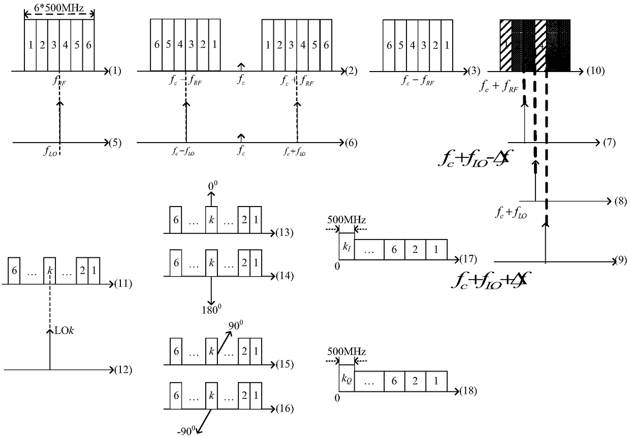
[0082] Step 1: According to figure 2 , when the input radio frequency signal is a 3GHz broadband microwave signal, if you want to obtain an intermediate frequency signal with a bandwidth of 500MHz and a center frequency of 750MHz. When the excitation signal of the first optical frequency shift is -500MHz, output the upper sideband signal of the first optical frequency shift (such as image 3 (12)) and the RF signal outp...


PUM


Abstract

The invention relates to a broadband multichannel channelization system and an implementation method based on an optical frequency shift, and belongs to the technical field of microwave photonics. Aninterference effect between electrooptical modulators and the optical frequency shift characteristic are utilized, and multi-channel division and high-rejection ratio same-intermediate-frequency frequency conversion of broadband microwave signals are completed. The invention proposes the broadband multi-channel channelization method based on the optical frequency shift by combining optical frequency shift channelization and I / Q down-conversion. According to the broadband multi-channel channelization method provided by the invention, a single-frequency laser is combined with a double-sided bandfrequency shift to complete the channel division of a broadband signal; and the output of several two-way same-intermediate-frequency signals which are mirrored to each other through the I / Q down-conversion is realized, which not only avoids the defect that light filtering out-of-band rejection capability is poor in traditional channelized receiving, but also avoids the defect that high-quality coherent optical comb implementation is complex in channelized receiving based on an optical frequency comb.

Description

technical field [0001] The invention relates to a broadband multi-channel channelization system and implementation method based on optical frequency shift, and belongs to the field of microwave photon technology. Background technique [0002] With the development of multi-band, large-bandwidth, and flexible-configurable multi-functional integrated satellite communication systems, the RF front-end as the core part needs to have transparent frequency bands, large working bandwidth, channelization and simultaneous frequency conversion of microwave signals in different working frequency bands. ability. At present, the traditional microwave technology is mainly used to channelize the received microwave signal for reception, frequency conversion and transmission. Limited by the bottleneck of microwave technology, the working bandwidth of microwave signal channelization is limited below GHz; the same structure is generally not compatible with different frequency bands, that is, it...

Claims


Application Information

Patent Timeline
Patent Type & Authority Applications(China)
IPC IPC(8): H04B7/185H04B10/112H04B10/50H04B10/516H04B10/548
CPCH04B7/1851H04B10/1121H04B10/503H04B10/5165H04B10/548
Inventor 蒋炜高永胜秦伟泽李小军谭庆贵禹旭敏梁栋朱忠博赵尚弘
Owner XIAN INSTITUE OF SPACE RADIO TECH
Learn More