Method for preventing steel clamping of single-machine-frame rolling mill

A single stand, rolling mill technology, applied in the safety equipment of rolls, metal rolling, metal rolling, etc., can solve the problems of large production capacity loss, affecting fuel consumption, and high equipment renovation costs, and achieve the requirements of reducing the furnace temperature, reducing Loss of production capacity and the effect of reducing loss of roll wear

Active Publication Date: 2018-10-16
BAOSHAN IRON & STEEL CO LTD
View PDF6 Cites 9 Cited by
  • Summary
  • Abstract
  • Description
  • Claims
  • Application Information

AI Technical Summary

Problems solved by technology

[0005] Disadvantages of the existing technology: (1) With the intensification of market competition, in order to enhance market competitiveness, high-strength products continue to increase, and accidents of R1 or R2 motor overcurrent tripping scrap steel occur frequently, resulting in huge loss of production capacity
(2) After the roll jams the steel, the roll surface is easily scalded, which has a serious impact on the roll consumption
(3) In order to reduce high-strength steel jamming accidents, the method of increasing the temperature of the slab can be adopted, but this will affect the fuel consumpt

Method used


Image

  • Method for preventing steel clamping of single-machine-frame rolling mill
  • Method for preventing steel clamping of single-machine-frame rolling mill
  • Method for preventing steel clamping of single-machine-frame rolling mill

Examples


Embodiment

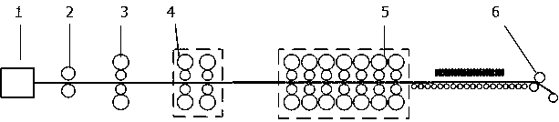
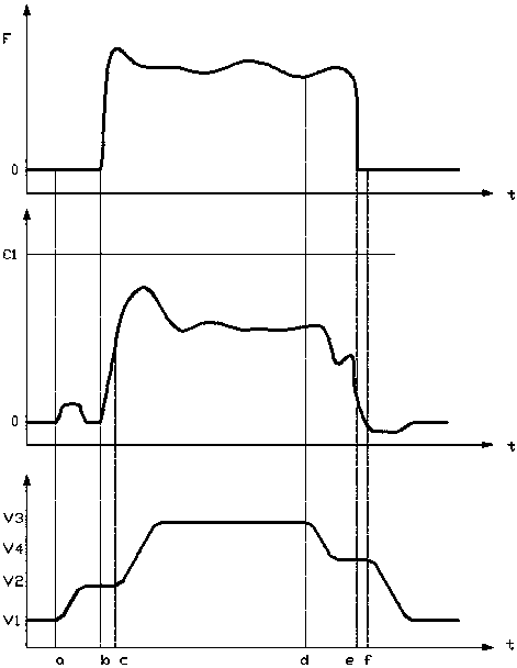
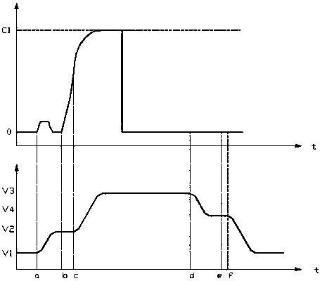
[0052] The method for preventing steel jamming in a single-stand rolling mill of a certain enterprise is implemented on the R2 frame of the 2050 hot-rolling line. The speed-down function start signal is judged by the basic automation computer L1 according to the actual value of the current sent by the transmission control unit: the system maximum current of the motor C1=9870A, take the current limit value C2 as 75%*C1. Then when the actual value of the motor current ≥ C2 (C2=75%*C1=7402.5A), the deceleration function is started, and the lower limit of the speed is 1m / s;

[0053] When reducing the speed given value of the rolling mill, in order to prevent the slab from slipping during the speed switching process, it is necessary to limit the maximum acceleration. In this embodiment, the acceleration is limited to 2m / s 2 .


PUM


Abstract

The invention discloses a method for preventing steel clamping of a single-machine-frame rolling mill. The method comprises the steps that firstly, a slab arrives at the front of a rolling mill entrance, the speed of the rolling mill is increased from the first speed V1 to the second speed V2; secondly, the head of the slab is bitten into the rolling mill; thirdly, the speed of the rolling mill isincreased from the second speed V2 to the third speed V3; fourthly, whether the actual current value of a motor in the rolling mill is larger than or equal to the current amplitude limiting C2 or notis judged, when the actual current value of the motor is larger than or equal to the current amplitude limiting C2, the speed reducing function of a basic automatic computer L1 is started, the basicautomation computer L1 is used for reducing the speed given value of the rolling mill, when the actual current value of the motor is lower than the current amplitude limiting value C2, reducing of thespeed given value is stopped until the tail of the slab is discharged out of the rolling mill, if the actual current value of the motor is still larger than or equal to the current amplitude limitingC2, the actual speed value of the rolling mill is reduced to the lowest speed amplitude limiting V1 until rolling is finished; and fifthly, when the actual current value of the motor is smaller thanthe current amplitude limiting C2, the tail of the slab arrives at the front of the rolling mill, the speed of the rolling mill is reduced from the third speed V3 to the second speed V2.

Description

technical field [0001] The invention relates to a hot rolling process, in particular to a method for preventing steel jamming in a single-stand rolling mill. Background technique [0002] The technological process of the hot rolling production line generally includes heating, rough rolling, finishing rolling, coiling and other processes, such as figure 1 shown. First, according to the rolling plan, the slabs are loaded into the walking heating furnace 1 in sequence. After the slabs are heated to the target temperature specified by the process, the slabs are drawn out sequentially by the steel pumping machine, placed on the roller table in front of the furnace, and then The hot slab is transported to the roughing mill. In the rough rolling unit, the slab first enters the R1 two-roll reversing mill for 2 rolling passes for 1-3 passes, then the slab enters the R2 four-roll reversing mill for 3 rolling passes for 3-7 passes, and then passes through the R3 And R4 rolling mill ...

Claims


Application Information

Patent Timeline
IPC IPC(8): B21B37/46B21B33/00
CPCB21B33/00B21B37/46
Inventor 幸利军李健
Owner BAOSHAN IRON & STEEL CO LTD
Why Eureka
Try Eureka