Integral wheel stamping and spinning manufacturing method

A manufacturing method and an integrated technology, applied in the manufacturing field, can solve the problems of difficulty, need more equipment, and the inability to optimize the thickness of the rim part, and achieve the effect of high surface accuracy, shape accuracy, and wall thickness optimization

Inactive Publication Date: 2018-10-16
BAOSHAN IRON & STEEL CO LTD
View PDF6 Cites 2 Cited by
  • Summary
  • Abstract
  • Description
  • Claims
  • Application Information

AI Technical Summary

Problems solved by technology

However, the rolling process used in this patent document is mainly suitable for forging parts. The rolling process is only used to reserve part of the rim material, and does not participate in the specific shape forming process. The rim part is still produced by the three-pass rolling process, which cannot be realized. The thickness of the rim part is optimized, and involves many process methods and requires a lot of equipment. The conventional rim rolling process cannot achieve the final dimensional accuracy, and a follow-up finishing process is still required to ensure the dimensional accuracy
At the same time, since this technical solution needs to roll the protruding material stored in rolling into a rim, it is very difficult and difficult to succeed.

Method used


Image

  • Integral wheel stamping and spinning manufacturing method
  • Integral wheel stamping and spinning manufacturing method
  • Integral wheel stamping and spinning manufacturing method

Examples


Embodiment 1-7

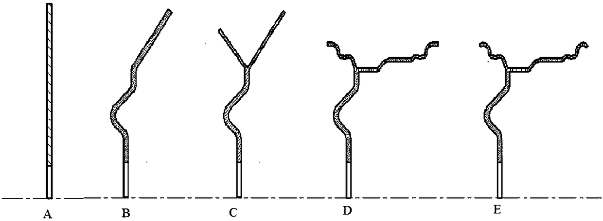
[0039] In Examples 1-7, figure 1 The specific steps of the forming process path of the integral wheel punching and spinning manufacturing method shown are as follows:

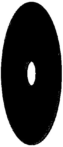
[0040] Step A: blanking and punching the center hole, see the three-dimensional structure of the blank formed in step A figure 2 ;

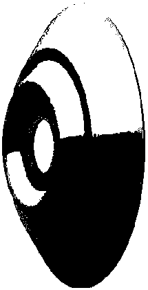
[0041] Step B: Stamping, please refer to Figure 7 ,Such as Figure 7 As shown, the blank 1 prepared by blanking and center punching is placed between the punching dies 2, 4 and pressed tightly. The middle part of the blank 1 is formed into a spoke shape, and the outer edge of the blank 1 is used to subsequently form the rim shape, step B The three-dimensional structure of the formed blank see image 3 ;

[0042] Step C: Wheel rim pre-spinning, its specific application is as Picture 8 As shown, the pre-spinning upper core mold 10 and the pre-spinning lower core mold 12 are used to clamp the blank 1, and the spinning upper core mold 10 and the spinning lower core mold 12 drive the blank...


PUM

PropertyMeasurementUnit
diameteraaaaaaaaaa
diameteraaaaaaaaaa

Abstract

The invention discloses an integral wheel stamping and spinning manufacturing method. The method comprises the following steps that (1) stamping is carried out, specifically, stamping is carried out on a blank so as to form a spoke part; (2) pre-spinning is carried out on a rim, specifically, the blank is clamped by adopting an upper pre-spinning mandrel and a lower pre-spinning mandrel, the upperpre-spinning mandrel and the lower pre-spinning mandrel drive the blank to rotate synchronously, and meanwhile, lateral extrusion force is applied to the outer edge of the blank by adopting an autorotation and radial feed type spinning wheel so as to form the outer edge of the blank into the V-shaped rim with an outward opening; (3) spinning forming is carried out on the rim, specifically, the blank is clamped by adopting an upper rim forming mandrel and a lower rim forming mandrel, the upper rim forming mandrel and the lower rim forming mandrel drive the blank to synchronously rotate, and meanwhile, pressure is applied to the two sides of the V-shaped rim by adopting an autorotation and radial feed type forming spinning wheel so as to enable the two sides of the V-shaped rim to be attached to the upper rim forming mandrel and the lower rim forming mandrel respectively; and (4) spinning is carried out on a wheel flange.

Description

Technical field [0001] The invention relates to a manufacturing method, in particular to a manufacturing method of an integral wheel. Background technique [0002] The steel wheel in the prior art is a single component that is welded and assembled by two parts, the middle part is the spoke part, and the outer ring part is the rim part. The two are separately manufactured and then assembled as a wheel by welding. In other words, the steel wheels in the prior art are all assembled from two steel parts, and no integral steel wheels have appeared in the market. [0003] The announcement number is CN104191900A, the announcement date is December 10, 2014, and the Chinese patent document titled "One-piece plate weldless wheel and its forming method" discloses a one-piece plate weldless wheel forming method. The technical solution disclosed in the patent document introduces a method for manufacturing an integrated plate weldless wheel with a rolling method. Compared with the traditional w...

Claims


Application Information

Patent Timeline
Patent Type & Authority Applications(China)
IPC IPC(8): B21D22/16B21D53/26B21D53/30
CPCB21D22/16B21D53/265B21D53/30
Inventor 肖华石磊李久茂张骥超
Owner BAOSHAN IRON & STEEL CO LTD
Why Eureka
Try Eureka