Device and packaging method for end sealing of deformable metal foil structure

A technology of end sealing and metal foil, which is applied in metal processing equipment, welding equipment, manufacturing tools, etc., can solve the problem of unreliable connection between deformable metal foil structure and flange, and solve the problem of low welding strength, Meet the application requirements, no air leakage effect

Inactive Publication Date: 2020-06-09
ZHEJIANG UNIVERSITY OF SCIENCE AND TECHNOLOGY
View PDF5 Cites 0 Cited by
  • Summary
  • Abstract
  • Description
  • Claims
  • Application Information

AI Technical Summary

Problems solved by technology

[0003] The purpose of the present invention is to solve the problem that the deformable metal foil structure and the flange cannot be reliably connected, and provide a device and packaging method for the end sealing of the deformable metal foil structure

Method used


Image

  • Device and packaging method for end sealing of deformable metal foil structure
  • Device and packaging method for end sealing of deformable metal foil structure
  • Device and packaging method for end sealing of deformable metal foil structure

Examples


specific Embodiment approach 1

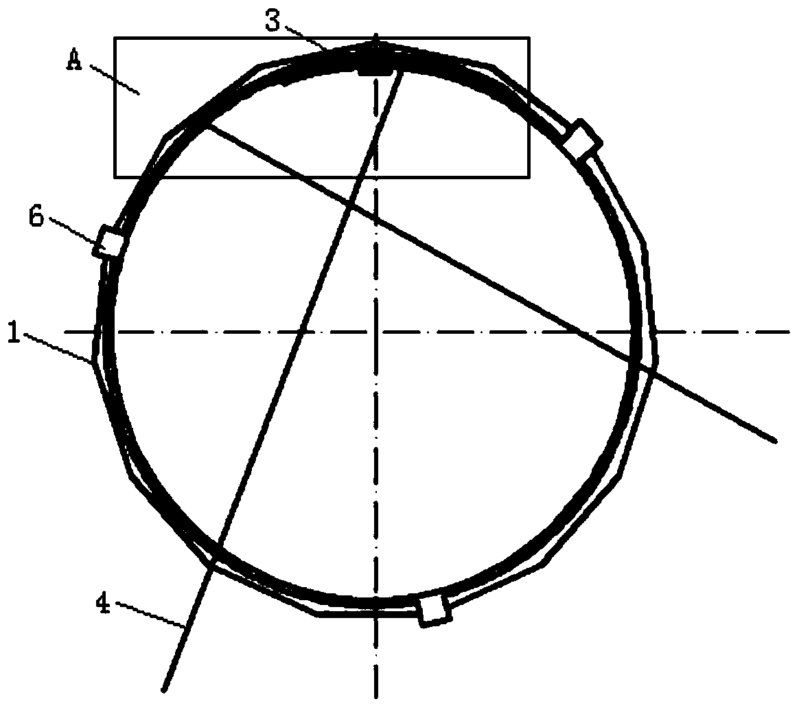
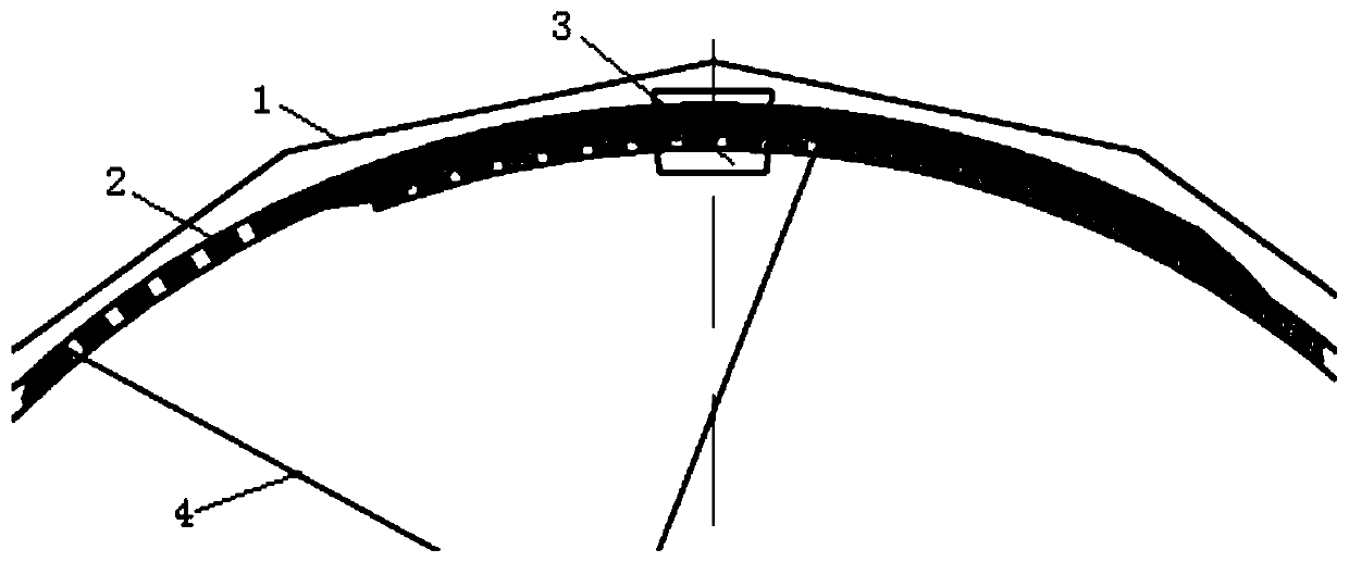
[0019] Embodiment 1: This embodiment is a device for sealing the end of a deformable metal foil structure, which includes a highly elastic metal foil 2, a lock 3, a flange 5 and several positioning pieces 6;

[0020] One end of the high elastic metal foil material 2 is set as an inner zigzag end, and several holes are arranged on the high elastic metal foil material 2 connected to the inner zigzag end, and the axial direction of the hole is in line with the high elastic metal The thickness direction of the foil material 2 is parallel; the other end of the highly elastic metal foil material 2 is set as an outer zigzag end, and several holes are arranged on the outer zigzag end, and the axis direction of the hole is the same as that of the outer zigzag end. The thickness direction is parallel; the highly elastic metal foil material 2 is interlocked with the inner serrated end and the outer serrated end through the lock 3 to form a highly elastic thin-walled metal ring, and the hi...

specific Embodiment approach 2

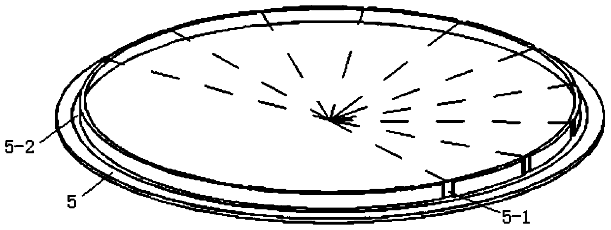
[0021] Embodiment 2: The difference between this embodiment and Embodiment 1 is: 10 micro-grooves 5-1 are arranged on the outer side of the tubular wall of the flange plate 5, except for the two adjacent micro-grooves 5-1 on the outermost side. , and the distances between the other two adjacent micro-grooves 5-1 along the circumferential direction are equal. Others are the same as the first embodiment.

specific Embodiment approach 3

[0022] Specific embodiment three: the difference between this embodiment and specific embodiment one or two is that: the diameter of the outer surface of the flange plate 5 tubular wall is 396mm, and the length of the miniature groove 5-1 is 5mm, and the width is 3mm. The distance between the outermost two adjacent micro-grooves 5-1 along the circumferential direction is 907 mm, and the distance between the other two adjacent micro-grooves 5-1 along the circumferential direction is 350 mm. Others are the same as those in Embodiment 1 or 2.


PUM

PropertyMeasurementUnit
diameteraaaaaaaaaa
thicknessaaaaaaaaaa
depthaaaaaaaaaa

Abstract

The invention provides a device and method for sealing the end part of a deformable metal foil material structure, and belongs to the field of precise connection of deformable ultra-thin metal structures, and particularly relates to a sealing device and a sealing method for the end part of a deformable metal foil material structure. The invention aims to solve the problem that the deformable metalfoil material structure and a flange cannot be reliably connected. The device for sealing the end part of the deformable metal foil material structure comprises a high-elasticity metal foil material,a lock catch, a flange plate and a plurality of positioning pieces. The sealing method comprises the following steps: 1, a high-elasticity thin-wall metal ring is formed; 2, the high-elasticity thin-wall metal ring is horizontally placed; 3, the end part of the deformable ultra-thin metal foil material structure is supported into a circle; and 4, the deformable metal foil material structure is arranged on a flange plate, and keeps warm in a nitrogen atmosphere in a heat treatment furnace and is cooled to the room temperature along with the furnace, so that the deformable ultra-thin metal foil material structure with the sealed end is obtained. The device is mainly used for sealing the end part of the deformable metal foil material structure.

Description

technical field [0001] The invention belongs to the field of precise connection of deformable ultra-thin metal structures, and in particular relates to a sealing device and a packaging method for the end of a deformable metal foil structure. Background technique [0002] The deformable ultra-thin metal structure can be folded into a small state on the ground and unfolded into a large state after reaching the destination. No damage occurs during folding and unfolding. Since this good folding performance meets the transportation requirements of aerospace devices with relatively simple structure and large size, it is widely used in aerospace. When this type of structure is used, several units are usually butted at the ends to form a complex, or the ends are hermetically connected to the spacecraft. However, due to the small material thickness and deformation resistance of the deformable metal foil structure, it is difficult to clamp when the end is welded, and the structure i...

Claims


Application Information

Patent Timeline
Patent Type & Authority Patents(China)
IPC IPC(8): B23K1/00B23K1/008
CPCB23K1/0008B23K1/008
Inventor 聂大明曹丽丽祝邦文郑军马红萍管爱枝
Owner ZHEJIANG UNIVERSITY OF SCIENCE AND TECHNOLOGY
Why Eureka
Try Eureka