Graphite concentrated hydrochloric acid production absorption tower

A technology of concentrated hydrochloric acid and desorption tower, which is applied in chemical/physical/physical chemical processes, chemical instruments and methods, chemical/physical processes, etc., can solve the problems of large packing factor, large internal space, high energy consumption rate, etc., and achieve improvement Cross-sectional porosity, improvement of flow state, and improvement of analysis efficiency

Inactive Publication Date: 2015-08-05
吉林市四通防腐设备有限责任公司
View PDF0 Cites 0 Cited by
  • Summary
  • Abstract
  • Description
  • Claims
  • Application Information

AI Technical Summary

Problems solved by technology

Due to the inherent defects of graphite material such as low strength and high brittleness; it cannot be processed into light and thin parts, so the structure of the internal parts of the graphite hydrochloric acid analysis tower is heavy and takes up a large internal space, especially the cross-sectional space; in addition, the graphite material is generally only Suitable for processing into Raschig rings
The mass transfer efficiency of the Raschig ring is low and the packing factor is large, so that the diameter of the graphite desorption tower is generally 40-60% larger than that of the metal tower with the same performance
On the other hand, due to the amplification effect of the packed tower, it leads to a vicious circle, that is, the larger the tower diameter, the lower the mass transfer efficiency, the higher the energy consumption rate, and the worse the product quality
Therefore, the traditional graphite-made concentrated hydrochloric acid desorption tower has disadvantages such as low desorption efficiency, high operating cost, and high water content in the product hydrogen chloride.

Method used


Image

  • Graphite concentrated hydrochloric acid production absorption tower

Examples


Embodiment Construction

[0024] Below in conjunction with accompanying drawing, the concentrated hydrochloric acid high-efficiency desorption tower made of graphite of the present invention is further explained.

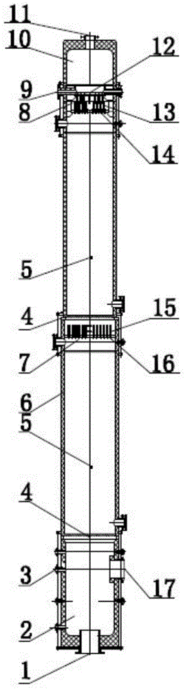
[0025] Such as figure 1 As shown, a kind of graphite-made concentrated hydrochloric acid high-efficiency analysis tower of the present invention comprises cylinder body 6, and the top of cylinder body 6 is provided with concentrated hydrochloric acid inlet 9, and the top of concentrated hydrochloric acid inlet 9 is provided with graphite upper seal head 10, and graphite upper seal head 10 The top of the top is provided with a hydrogen chloride outlet 11, and the graphite upper head 10 is sealed and fixedly connected with the cylinder body 6;

[0026] A liquid initial distributor 12 is installed inside the cylinder 6 corresponding to the concentrated hydrochloric acid inlet 9, which is fixedly connected to the cylinder 6. A liquid distributor 8 is provided below the liquid initial distributor...


PUM


Abstract

A graphite concentrated hydrochloric acid production absorption tower comprises a cylinder. A concentrated hydrochloric acid inlet is formed in the upper portion of the cylinder, and a diluted hydrochloric acid steam inlet is formed in the lower portion. A plurality of support plates are fixedly connected into the cylinder, and detection holes are formed at the corresponding positions on the outside of the cylinder. A graphite upper seal head is arranged above the cylinder and is in seal fixed connection with the cylinder. A graphite lower seal head is arranged below the cylinder and is in seal fixed connection with the cylinder. Graphite packing of certain height is stacked above the support plates respectively and is disposed in the cylinder to divide the absorption tower into a plurality of graphite packing sections. A liquid distributor is arranged on the upper portion of the graphite packing section at the top end and is fixedly connected with the cylinder. A liquid re-distributor is arranged on the upper portions of the other graphite packing sections respectively and is fixedly connected with the cylinder. A liquid initial distributor is arranged at the upper end of the liquid distributor and is arranged in the cylinder and fixedly connected with the cylinder. The absorption tower has the advantages of being high in absorption efficiency, low in fabrication cost, high in anti-corrosion capacity and low in operation cost.

Description

technical field [0001] The invention belongs to the technical field of chemical equipment, and in particular relates to a high-efficiency analysis tower for concentrated hydrochloric acid made of graphite. Background technique [0002] Concentrated hydrochloric acid desorption tower is a common equipment in the production of high-purity hydrochloric acid or high-quality PVC industry; graphite material is especially suitable for the production of anti-corrosion equipment in chlor-alkali industries such as hydrochloric acid due to its unique corrosion resistance. Traditional graphite analysis towers use graphite materials to make tower internals. Due to the inherent defects of graphite material such as low strength and high brittleness; it cannot be processed into light and thin parts, so the structure of the internal parts of the graphite hydrochloric acid analysis tower is heavy and takes up a large internal space, especially the cross-sectional space; in addition, the graph...

Claims


Application Information

Patent Timeline
Patent Type & Authority Applications(China)
IPC IPC(8): B01J19/00
Inventor 孟海波宁永林
Owner 吉林市四通防腐设备有限责任公司
Why Eureka
Try Eureka