

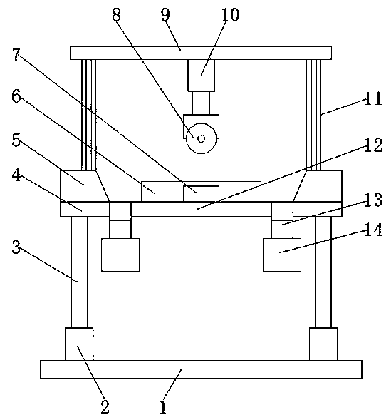
Metal cutting machine tool convenient to clean
A metal cutting and machine tool technology, applied in metal processing machinery parts, metal processing equipment, maintenance and safety accessories, etc., can solve the problems of production and living environment pollution, easy scattering of iron filings, occupying a large space, etc., to protect safety, improve The effect of cleaning, the effect of improving production efficiency
- Summary
- Abstract
- Description
- Claims
- Application Information
AI Technical Summary
Problems solved by technology
Method used
Image

Examples
Embodiment 1
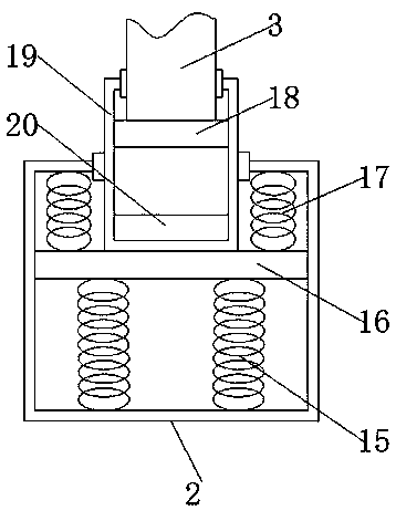
[0026] Example 1 please refer to figure 2The bottom of the damping device 2 inner chamber is fixedly connected with a first damping spring 15, the top of the first damping spring 15 is fixedly connected with a fixed plate 16, and the center of the top of the fixed plate 16 is fixedly connected with a magnet damping cylinder 19. The top of the plate 16 and the outside of the magnet damping cylinder 19 are fixedly connected with a second damping spring 17, and the top of the second damping spring 17 is fixedly connected with the top of the vibration damping device 2 inner cavity, and the inner cavity of the magnet damping cylinder 19 The bottom of the bottom is fixedly connected with the first lower magnet 20, the top of the first lower magnet 20 is provided with the first upper magnet 18, the top of the first upper magnet 18 is fixedly connected with the support leg 3, the upper magnetic pole of the first lower magnet 20 and the first The lower magnetic pole of an upper magnet...
Embodiment 2
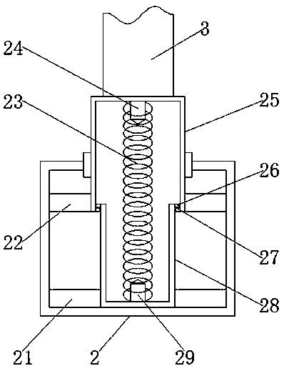
[0027] Example 2 please refer to image 3 The bottom of the inner cavity of the damping device 2 is fixedly connected with an inner cylinder 28, the bottom of the inner cavity of the damping device 2 is fixedly connected with a second lower magnet 21 on the outside of the inner cylinder 28, and the bottom of the inner cavity of the inner cylinder 28 is fixedly connected with a The lower mounting column 29, the top of the lower mounting column 29 is fixedly connected with the third damping spring 23, the top of the third damping spring 23 is fixedly connected with the upper mounting column 24, and the top of the upper mounting column 24 is fixedly connected with the outer cylinder 25, The bottom of the inner side of the outer cylinder 25 is fixedly connected with a first stopper 27, the top of the outer side of the inner cylinder 28 is fixedly connected with a second stopper 26, and the bottom of the outer side of the outer cylinder 25 is fixedly connected with a second upper ma...
PUM
 Abstract
Description
Claims
Application Information