Continuous polystyrene board cutting machine

A cutting machine and polystyrene board technology, which is applied in metal processing and other directions, can solve the problems of high cutting wire length requirements, large physical exertion of workers, and uneven stress on polystyrene boards, so as to avoid workers walking back and forth and short lengths. , The effect of stable transmission speed

Inactive Publication Date: 2018-10-16
天津宇屹新材料科技发展有限公司
View PDF0 Cites 0 Cited by
  • Summary
  • Abstract
  • Description
  • Claims
  • Application Information

AI Technical Summary

Problems solved by technology

[0002] In the traditional polystyrene board cutting process, the intermittent cutting method is used to complete several processes in sequence on a stationary platform. The cutting time is long, and the staff needs to walk back and forth on various positions, which wastes time and is harmful to the staff. The physical consumption is relatively large. The cutting wire of the traditional polystyrene board cutting device is usually parallel to the work surface. When cutting, the cutting wire moves downward, and the cutting wire presses the polystyrene board, which easily causes uneven force on the upper and lower sides of the polystyrene board. It is easy to bend and deform the cut product during cutting, and the traditional cutting method requires a high length of cutting wire, which increases the cost

Method used


Image

  • Continuous polystyrene board cutting machine
  • Continuous polystyrene board cutting machine
  • Continuous polystyrene board cutting machine

Examples


Embodiment Construction

[0019] The following will clearly and completely describe the technical solutions in the embodiments of the present invention with reference to the accompanying drawings in the embodiments of the present invention. Obviously, the described embodiments are only some, not all, embodiments of the present invention.

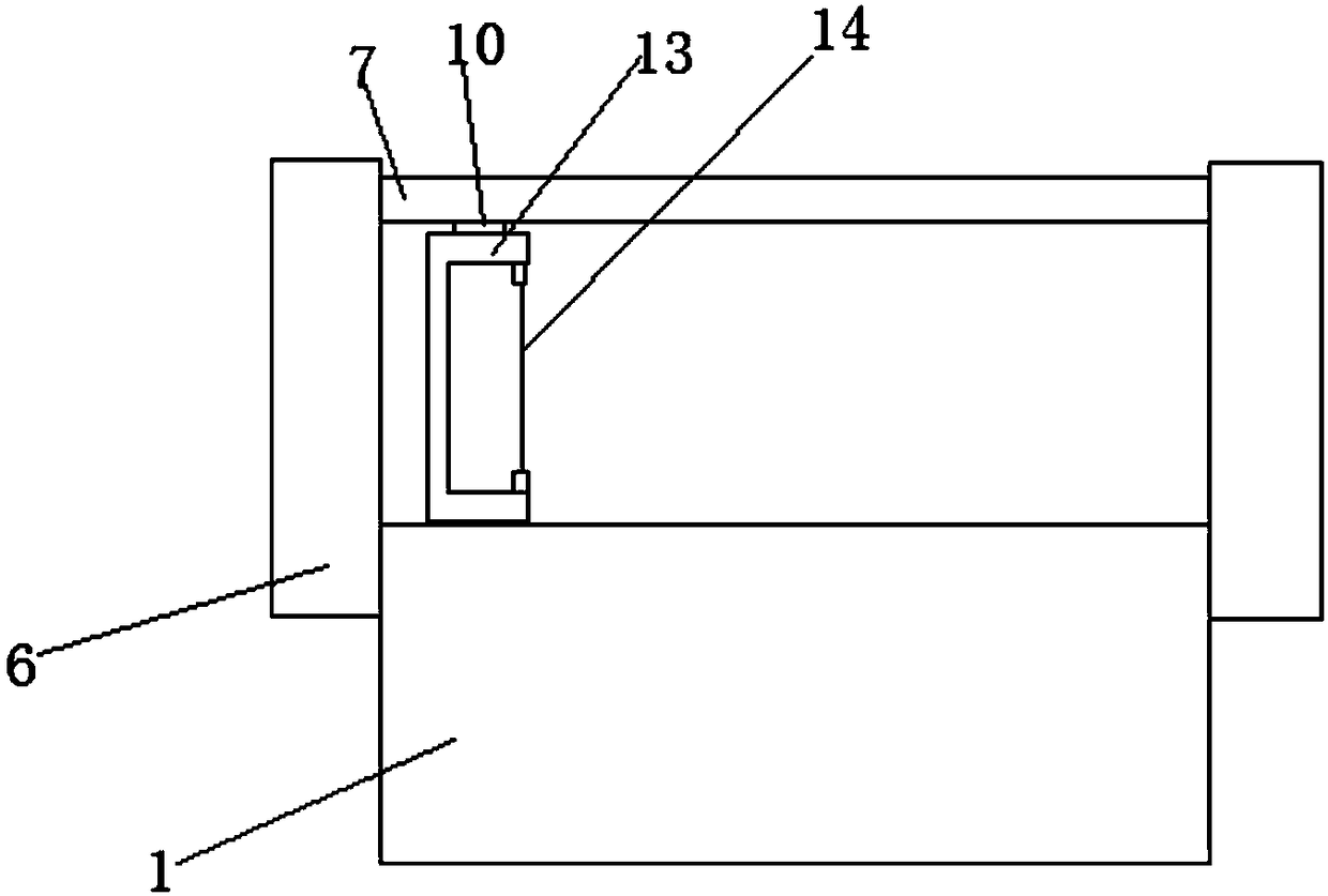
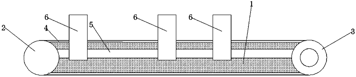
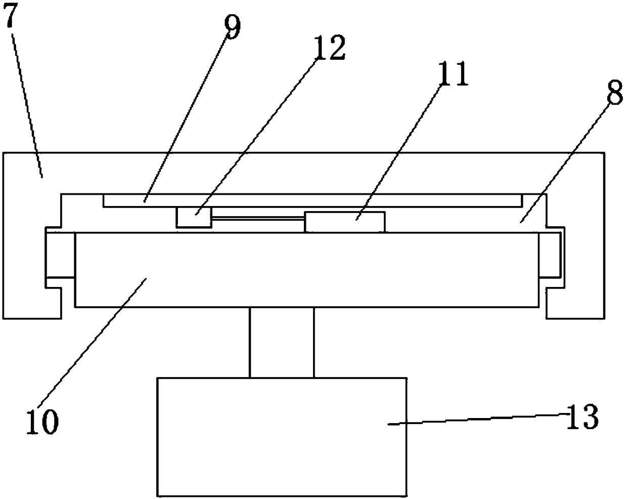
[0020] refer to Figure 1-3 , a continuous polystyrene board cutting machine, including a workbench 1, a beam 7 and a fixed frame 13, a motor 2 is fixed on one side of the workbench 1, and the end of the workbench 1 away from the motor 2 is rotatably connected to a roller 3, and the motor 2 The first gear is sleeved on the output shaft of the motor, the outer wall of the roller 3 is sleeved with a toothed plate, and the motor 2 is connected to the roller 3 through a chain, and the chain is connected with a conveyor belt. Both are provided with the first chute 5, and a plurality of support rods 6 are slidably installed in the two first chute 5, and the support rods 6 ...


PUM


Abstract

The invention discloses a continuous polystyrene board cutting machine. The continuous polystyrene board cutting machine comprises a workbench, wherein a motor is fixed on one side of the workbench, arolling shaft is rotationally connected to the end, far away from the motor, of the workbench, a first gear sleeves an output shaft of the motor, a toothed disc sleeves the outer wall of the rollingshaft, a chain is connected between the first gear and the toothed disc, and a conveyor belt is arranged on the chain; and a first sliding chute is formed in the outer wall of each of the two sides ofthe workbench, the two first sliding chutes are each internally provided with a plurality of supporting rods in a sliding mode, and cross beams located above the workbench are connected between the supporting rods. According to the continuous polystyrene board cutting machine, the workers do not need to walk back and forth, the labor intensity of workers is reduced, the time is saved, and the working efficiency is improved; the length of a vertically-arranged electric heating cutting wire is shorter, so that the cost is saved; and the electric heating cutting wire can vibrate up and down during cutting, so that the heat of the electric heating cutting wire is evenly transmitted to a cutting surface, and the cutting speed is increased.

Description

technical field [0001] The invention relates to the technical field of cutting machines, in particular to a continuous polystyrene board cutting machine. Background technique [0002] In the traditional polystyrene board cutting process, the intermittent cutting method is used to complete several processes in sequence on a stationary platform. The cutting time is long, and the staff needs to walk back and forth on various positions, which wastes time and is harmful to the staff. The physical consumption is relatively large. The cutting wire of the traditional polystyrene board cutting device is usually parallel to the work surface. When cutting, the cutting wire moves downward, and the cutting wire presses the polystyrene board, which easily causes uneven force on the upper and lower sides of the polystyrene board. It is easy to bend and deform the cut product during cutting, and the traditional cutting method has a higher requirement on the length of the cutting wire, which...

Claims


Application Information

Patent Timeline
Patent Type & Authority Applications(China)
IPC IPC(8): B26F3/12B26D7/26B26D5/08
CPCB26F3/12B26D5/086B26D7/2614
Inventor 沙淮晴
Owner 天津宇屹新材料科技发展有限公司
Why Eureka
Try Eureka