
Hydraulic fork truck

A forklift and hydraulic technology, applied in the field of hydraulic forklifts, can solve the problems of shortened service life of anti-skid parts, impact damage of anti-skid parts, goods sliding off the forklift, etc., and achieve the effect of extending service life, reducing impact damage, and simple and convenient replacement.

Inactive Publication Date: 2018-10-16
海宁市高级技工学校
View PDF6 Cites 2 Cited by
  • Summary
  • Abstract
  • Description
  • Claims
  • Application Information

AI Technical Summary

Problems solved by technology

With the development of modern construction, the use of forklifts is becoming more and more common, but after a long period of use, it is found that there is a defect in the existing hydraulic forklifts: when the bottom surface of the cargo is smooth and the friction with the surface of the forklift is small Uneven roads or slopes may cause goods to slide off the forklift, causing safety accidents or property damage
[0004] However, this kind of forklift also has the following problems in actual use: 1. The anti-slip part anti-slip rubber is fixed on the vehicle plate by pasting, and once damaged, it needs to be completely replaced, and the replacement is extremely troublesome
2. When using a forklift to insert and remove items in daily life, the items with larger mass will cause great impact damage and extrusion damage to the anti-skid parts, resulting in shortened service life of the anti-skid parts

Method used


Image

  • Hydraulic fork truck
  • Hydraulic fork truck
  • Hydraulic fork truck

Examples


Embodiment Construction

[0020] The present invention is described in further detail below:

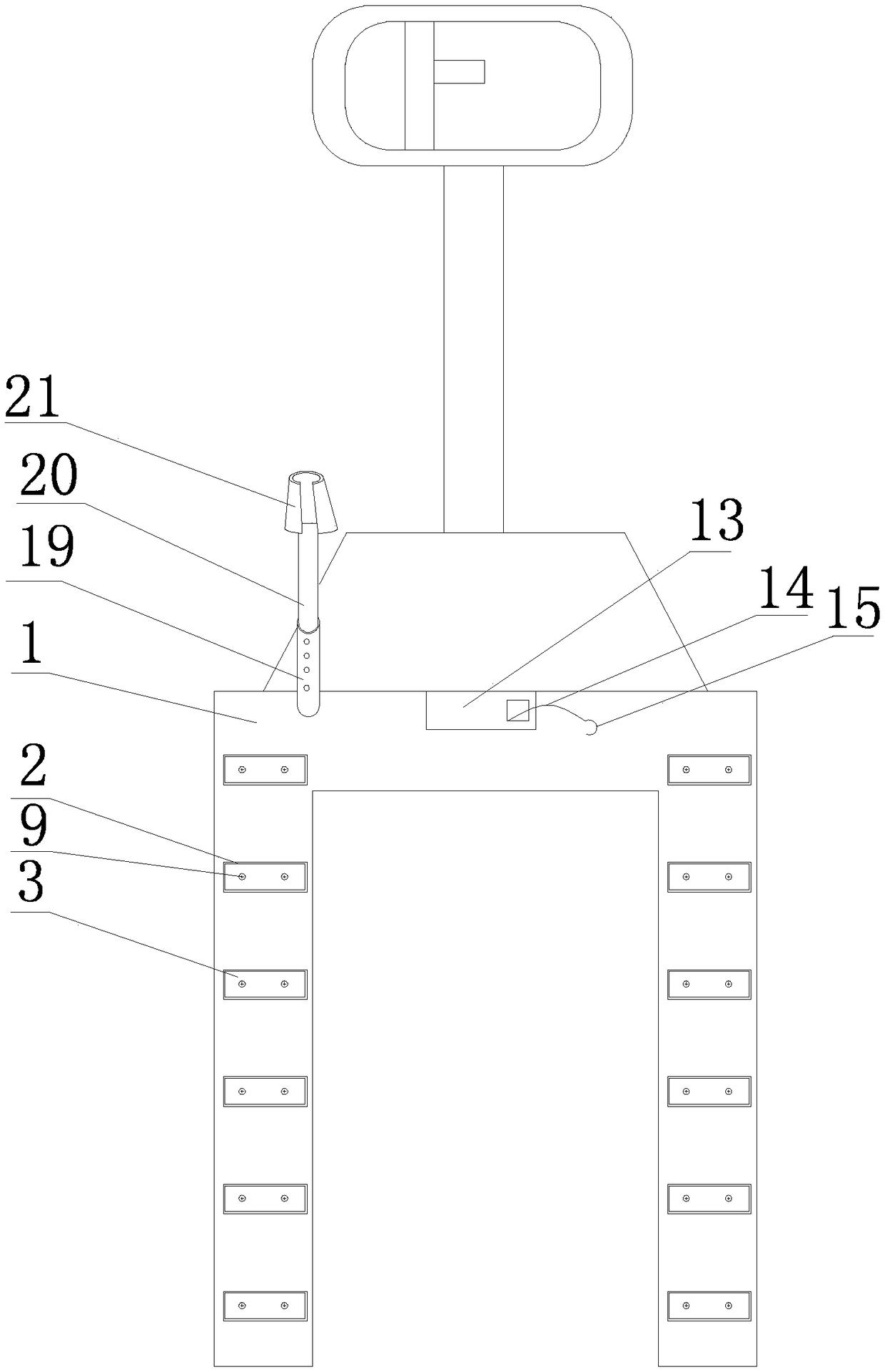
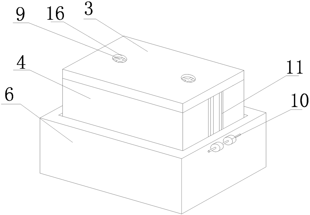
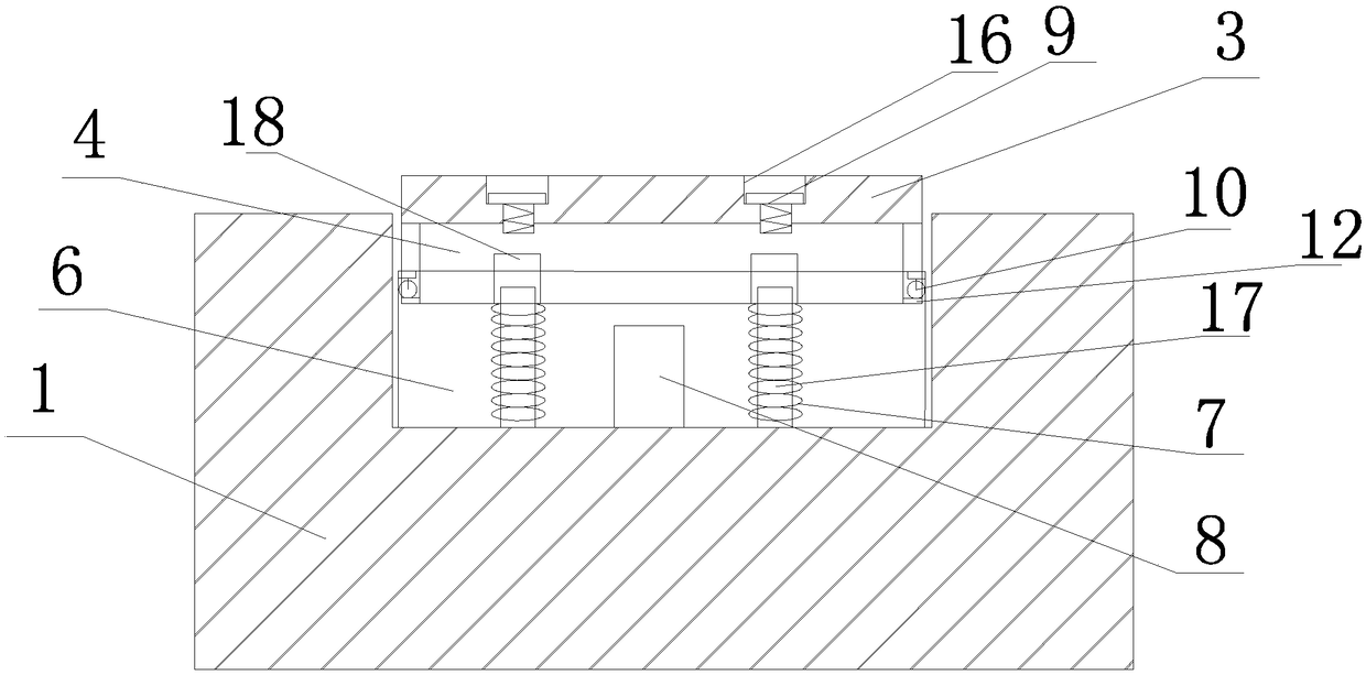
[0021] The forklift of the present invention comprises a hydraulic forklift body, the vehicle plate 1 of the hydraulic forklift is provided with a plurality of grooves 2 uniformly distributed along the length direction of the vehicle plate 1, and each groove 2 is provided with a rubber block 3 And a buffer mechanism for buffering after the rubber block 3 is under pressure, the buffer mechanism includes an upper shell 4 and a lower shell 6 that are movably nested in each other, and a spring that is arranged in the lower shell 6 to play a buffering role 7. The guide column 17 arranged in the lower housing 6, the guide hole 18 arranged at the bottom of the upper housing 4 and matched with the guide column 17, the spring 7 is sleeved on the guide column 17, the lower end of the spring 7 and the lower housing 6, the inner bottom surface is attached, the upper end of the spring 7 is attached to the bottom of the up...


PUM


Abstract

The invention provides a hydraulic fork truck. Antiskid components on the hydraulic fork truck are convenient to replace, impacting damage and crushing damage on the antiskid components when objects are inserted and taken can be reduced simultaneously, and the service lives of the antiskid components are prolonged. The hydraulic fork truck comprises a hydraulic fork truck part; a plurality of grooves uniformly distributed in the length direction of a truck plate are formed in the truck plate of the hydraulic fork truck part; a rubber block and a buffering mechanism are arranged in each groove;each buffering mechanism is used for exerting the buffering effect after each rubber block is under the pressure; each buffering mechanism comprises an upper housing body, a lower housing body, springs, guide columns and guide holes; each upper housing body and each lower housing body movably sleeve with each other; the springs are arranged in each lower housing body and exert the buffering effect; the guide columns are arranged in each lower housing body; the guide holes fitting with the guide columns are formed in the bottom of each upper housing body; the springs sleeve the guide columns;the lower ends of the springs are bonded with the inner bottom surface of each lower housing body; the upper ends of the springs are bonded with the bottom of each upper housing body; each rubber block is detachably fixed to the upper surface of each upper housing body through bolts; a supporting column is arranged in each lower housing body; and an illuminating device is arranged on the truck plate of the hydraulic fork truck part further.

Description

technical field [0001] The invention relates to the mechanical field, in particular to a hydraulic forklift. Background technique [0002] Forklifts are important equipment in the logistics industry. They are small in size, light in weight, compact in structure, low in noise, low in pollution, flexible in operation, and can operate in a small space on the workplace. With the development of modern construction, the use of forklifts is becoming more and more common, but after a long period of use, it is found that there is a defect in the existing hydraulic forklifts: when the bottom surface of the cargo is smooth and the friction with the surface of the forklift is small Uneven roads or slopes may cause goods to slip off the forklift, causing safety accidents or property damage. [0003] There is a new type of manual hydraulic forklift with a patent number of 201220028359.6, which includes a hydraulic forklift. Boss. This solution uses anti-slip rubber and the boss on the ...

Claims


Application Information

Patent Timeline
Patent Type & Authority Applications(China)
IPC IPC(8): B66F9/075B66F9/12F21V33/00F21W131/40
CPCB66F9/07504B66F9/12F21V33/00F21W2131/40
Inventor 杨胜李叶金江褚佳琪
Owner 海宁市高级技工学校
Learn More