Built-in type deoxygenization machine

A deaerator, built-in technology, used in chemical instruments and methods, heating water/sewage treatment, degassed water/sewage treatment, etc., can solve problems such as poor operating performance, difficult maintenance, energy waste, etc., and achieve load adaptation. Good performance, low maintenance workload and high deoxidization efficiency

Pending Publication Date: 2018-10-16
XUELANG ELECTRIC POWER EQUIP XISHAN
View PDF5 Cites 1 Cited by
  • Summary
  • Abstract
  • Description
  • Claims
  • Application Information

AI Technical Summary

Problems solved by technology

[0003] At present, the widely used deaerator is the membrane deaerator, but the membrane deaerator is composed of an external deaerator head and a water tank. The water tank has a complex structure, large volume, poor operating performance, and requires a large installation space. The manufacturing and installation costs are relatively high, the core oxygen removal parts in the oxygen removal head are fixed and cannot be disassembled, difficult to overhaul and poor in operation stability
Since it is composed of an independent deaeration head and a water storage tank, the overall height of the equipment is high, and it needs to be transported separately and assembled on site, which has the problem of difficult transportation and assembly. The internal structure of the deaeration head is complex, consisting of a spiral membrane tube, a filler, and a distribution plate and other components, which have the problems of high failure rate and inconvenient maintenance
The water spray tray of the traditional thermal deaerator cannot ensure good atomization or filmization of water during low-load operation, resulting in poor water heating effect by heating steam and poor gas-water separation effect, so that oxygen cannot be effectively removed
The weight of the deaerator head, the large opening and the force and thermal stress caused by the steam temperature need to be considered in the design of the water storage tank of the traditional thermal deaerator, which will increase the thickness of the water storage tank and increase the steel consumption
While the traditional thermal deaerator discharges oxygen, it also releases a large amount of water vapor at the same time, which has a serious problem of energy waste

Method used


Image

  • Built-in type deoxygenization machine
  • Built-in type deoxygenization machine
  • Built-in type deoxygenization machine

Examples


Embodiment Construction

[0038] The present invention will be further described now in conjunction with accompanying drawing.

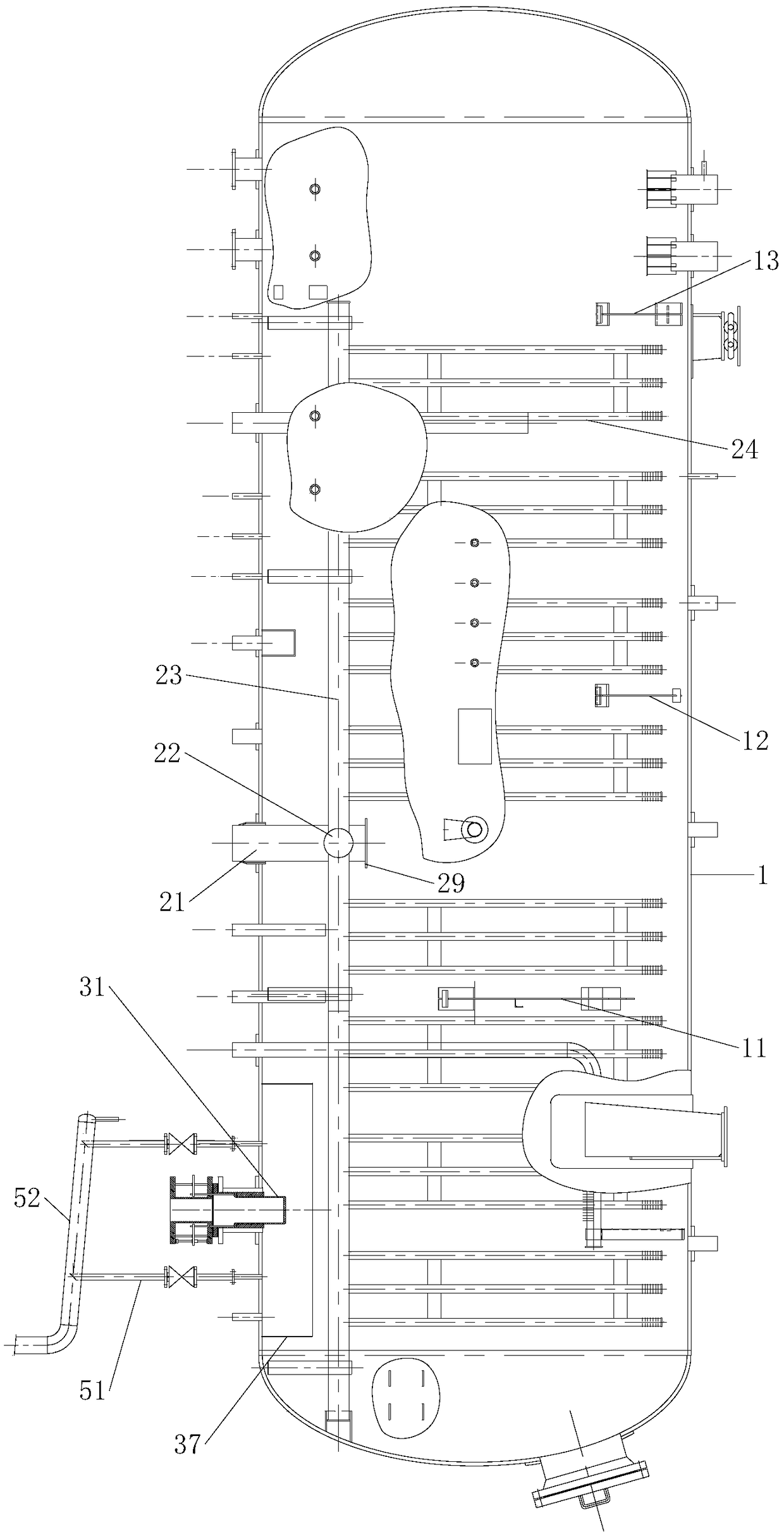
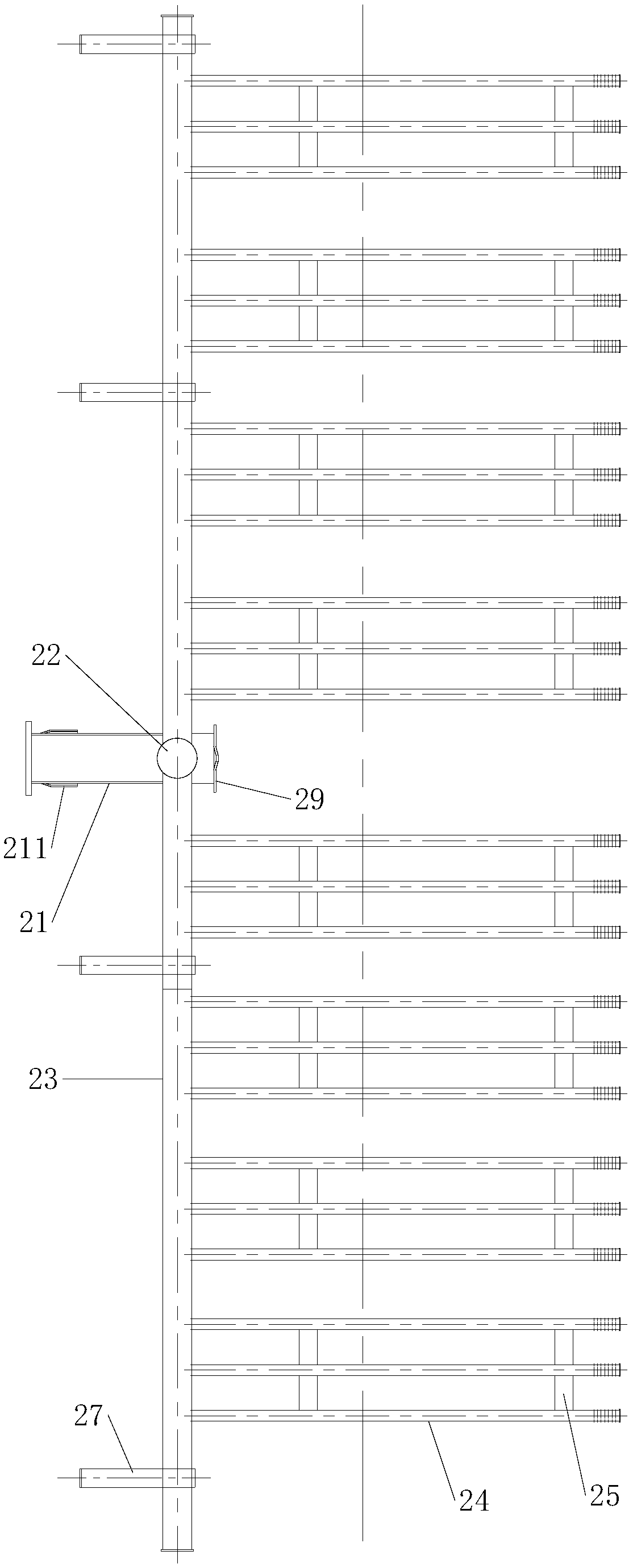
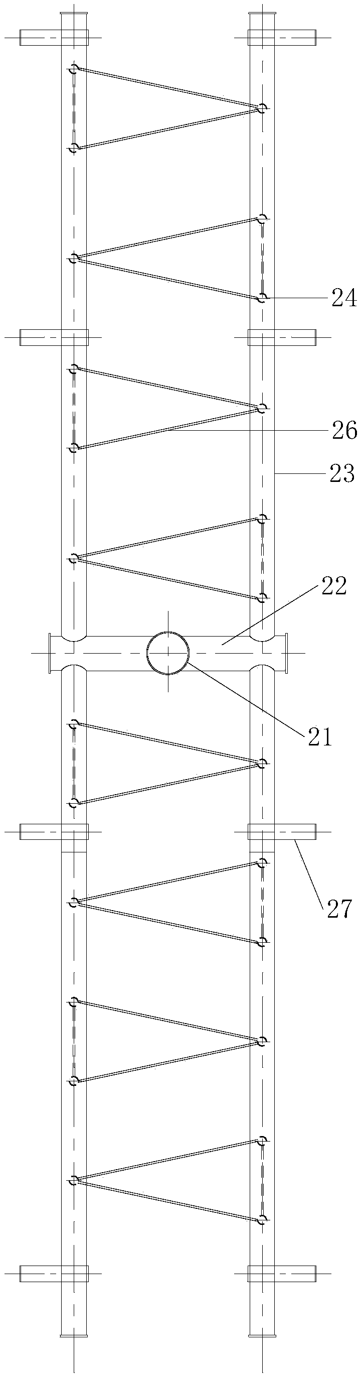
[0039] like Figure 1 to Figure 12 As shown, the built-in deaerator includes a deaeration tank 1, a condensate water inlet device and an exhaust device installed on the top of the deaeration tank 1, and a heating steam pipe located inside the deaeration tank 1; the deaeration tank 1 is Horizontal tank, the condensate water inlet device is located at one end of the deaeration tank 1, the exhaust device is located on the side of the condensate water inlet device; the air inlet of the steam pipe is fixed on the top of the deaeration tank 1, and the gas outlet is located below the liquid surface .

[0040] like Figure 12As shown, the exhaust device includes an exhaust main pipe 52, an exhaust branch pipe 51 and an exhaust valve 55; the exhaust branch pipe 51 is fixed on both sides of the condensed water inlet device, and the exhaust branch pipe 51 communicates with the exhaust...


PUM


Abstract

The invention relates to a deoxygenization machine, in particular to a built-in type deoxygenization machine. The built-in type deoxygenization machine comprises a deoxygenization tank, a condensed water inlet device and an air exhausting device mounted at the top of the deoxygenization tank, and a heating steam pipe located in the deoxygenization tank; the deoxygenization tank is a horizontal tank, the condensed water inlet device is located at one end of the deoxygenization tank, and the air exhausting device is located on the side face of the condensed water inlet device; and an air inlet of the steam pipe is fixed to the top of the deoxygenization tank, and an air outlet is located below the liquid level. The built-in type deoxygenization machine is compact in structure and small in size, can control the flux and maintain the constant pressure, and is high in heat exchange efficiency, high in deoxygenization efficiency, stable in deoxygenization, convenient to operate, good in loadadaptability, low in maintenance workload, low in cost and high in efficiency.

Description

technical field [0001] The invention relates to a deaerator, especially a built-in deaerator. Background technique [0002] At present, conventional deaerators with deaerator heads are generally used in domestic thermal power plants. Its types include rotary film type, spray packing type, water spraying disc type, etc.; installation types include vertical deaerator head and horizontal type. There are two kinds of deoxygenation heads. The oxygen removal process is completed in the oxygen removal head, including the preliminary oxygen removal in the spin film section (spray layer), which can remove most of the gas in the water, and the deep oxygen removal in the packing layer or water spray tray below, and the water out of the water. residual gas. [0003] At present, the widely used deaerator is the membrane deaerator, but the membrane deaerator is composed of an external deaerator head and a water tank. The water tank has a complex structure, large volume, poor operating p...

Claims


Application Information

Patent Timeline
Patent Type & Authority Applications(China)
IPC IPC(8): C02F1/02C02F1/20
CPCC02F1/02C02F1/20C02F2201/002
Inventor 杨鹤林
Owner XUELANG ELECTRIC POWER EQUIP XISHAN
Why Eureka
Try Eureka