Transformer wire placement rack and method of using the same

A technology for placing racks and transformers, which is applied in the manufacture of inductors/transformers/magnets, circuits, electrical components, etc. It can solve problems such as equipment shaking, shaft shaking, and changes, and achieve the effect of convenient transfer and avoiding movement

Pending Publication Date: 2018-10-16
浙江派尔电气有限公司
View PDF8 Cites 8 Cited by
  • Summary
  • Abstract
  • Description
  • Claims
  • Application Information

AI Technical Summary

Problems solved by technology

[0002] In the process of transformer production, the purchased whole tube of wires needs to be erected on the transformer wire rack, and the workers pull out the wires so that the shaft tube of the whole drum of wires rotates on the transformer wire rack, and the pulled out wires can be used In the process of transformer production, but the cross-sectional diameter of the rotating shaft is different from the inner diameter of the shaft barrel, which causes the shaft barrel to shake on the shaft, and because the wires wound on the shaft barrel are too heavy, the shaft is easy to shake and the whole equipment shakes. And through the setting of the friction plate, it is possible to adjust the rotation speed of the shaft cylinder on the transformer wire placeme

Method used


Image

  • Transformer wire placement rack and method of using the same
  • Transformer wire placement rack and method of using the same
  • Transformer wire placement rack and method of using the same

Examples


Embodiment Construction

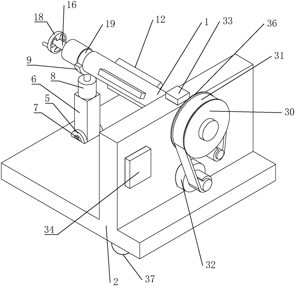
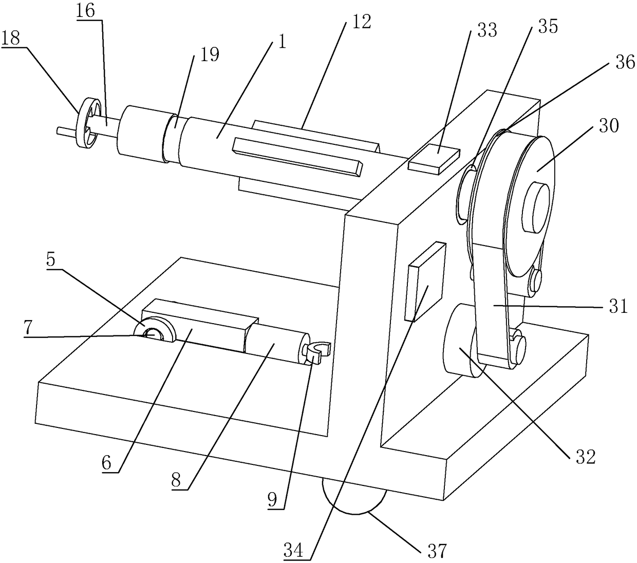
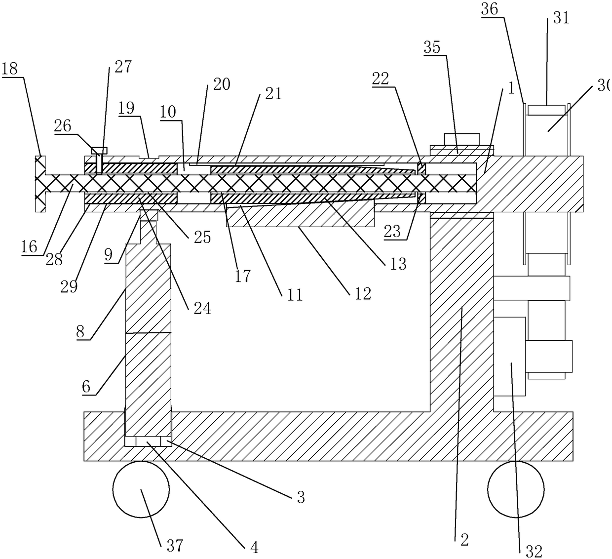
[0040] refer to Figures 1 to 5 As shown, a transformer wire placement frame and its use method of the present embodiment include a frame 2, a rotating shaft 1, a friction disc 30, a friction strip 31, a servo motor 32, a sensor 33, and a controller 34. The rotating shaft 1 is rotatably installed on the frame 2, the rotating shaft 1 includes one end for placing the shaft cylinder and the other end for installing the braking end of the friction disc 30, the shaft center of the friction disc 30 is in contact with the rotating shaft 1 The moving end is installed with the center of the shaft, the servo motor 32 is installed on the frame 2 and the rotating shaft 1 of the servo motor 32 is on one side of the friction disc 30, one end of the friction strip 31 is fixed on the frame 2 and the other end is rolled After bypassing the friction disc 30, it is connected to the rotating shaft 1 of the motor. The sensor 33 is installed on the frame 2 and is used to detect the rotational load ...


PUM


Abstract

The invention discloses a transformer wire placement rack and a method of using the same, the technical scheme is characterized by comprising a rack, a rotating shaft, a friction disc, a friction strip, a servo motor, a sensor and a controller, wherein a square groove is arranged at one end of the rack directly facing the rotating shaft protruding from the shaft barrel; a square rod is arranged inthe square groove in a sliding manner; a hydraulic cylinder is arranged at one end of the square rod away from the square groove; a semicircular bearing matched with the rotating shaft is arranged atthe top end of a piston rod of the hydraulic cylinder; a sliding block is mounted in a through groove in a sliding mode, a push block is installed in a circular cavity in a sliding mode, and a screwis mounted in the circular cavity in a rotating mode. According to the transformer wire placement rack, the rotating shaft can be dynamically loaded and output, the situation that the output load andthe preset parameters are the same in the wire drawing process are improved, the product quality rate and the production efficiency are improved, the stability of the shaft barrel on the rotating shaft can be improved, and the shaking situation of the rotating shaft on the rack can be avoided.

Description

technical field [0001] The invention relates to a transformer electric wire placing frame and a using method thereof. Background technique [0002] In the process of transformer production, the purchased whole tube of wires needs to be erected on the transformer wire rack, and the workers pull out the wires so that the shaft tube of the whole drum of wires rotates on the transformer wire rack, and the pulled out wires can be used In the process of transformer production, but the cross-sectional diameter of the rotating shaft is different from the inner diameter of the shaft barrel, which causes the shaft barrel to shake on the shaft, and because the wires wound on the shaft barrel are too heavy, the shaft is easy to shake and the whole equipment shakes. And through the setting of the friction plate, it is possible to adjust the rotation speed of the shaft cylinder on the transformer wire placement frame and the strength required for the wire to be pulled out. However, the cu...

Claims


Application Information

Patent Timeline
IPC IPC(8): H01F41/066H01F41/096
Inventor 黄宏斌陈佩芬
Owner 浙江派尔电气有限公司
Why Eureka
Try Eureka