
Double-layer induction cooker

An induction cooker, double-layer technology, applied in the field of induction cooker, can solve the problems of not being able to have heating and power saving at the same time, no power saving, single heat source, etc.

Inactive Publication Date: 2018-10-16
陈永航
View PDF1 Cites 2 Cited by
  • Summary
  • Abstract
  • Description
  • Claims
  • Application Information

AI Technical Summary

Problems solved by technology

It can overcome the problem that the traditional induction cooker only provides a single heat source
The double-layer induction cooker is composed of a large induction cooker body and a small induction cooker body. The lower surface of the large induction cooker body is provided with two concave chutes, and the upper surface of the small induction cooker body is provided with two convex slide rails. The rails are compatible with each other. There is a wire belt between the left side of the large induction cooker body and the left side of the small induction cooker body. The large induction cooker body and the small induction cooker body are in a sliding connection. There is No. 2 control circuit main board inside the body, and the No. 1 control circuit main board and No. 2 control circuit main board are connected in parallel through wires. The existing technology cannot have the functions of heating and power saving at the same time, and can not save energy while heating in double layers. Electricity

Method used


Image

  • Double-layer induction cooker
  • Double-layer induction cooker

Examples


Embodiment Construction

[0016] In order to make the technical means, creative features, goals and effects achieved by the present invention easy to understand, the present invention will be further described below in conjunction with specific embodiments.

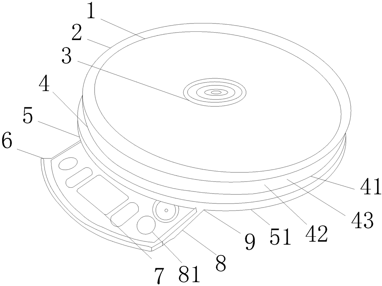
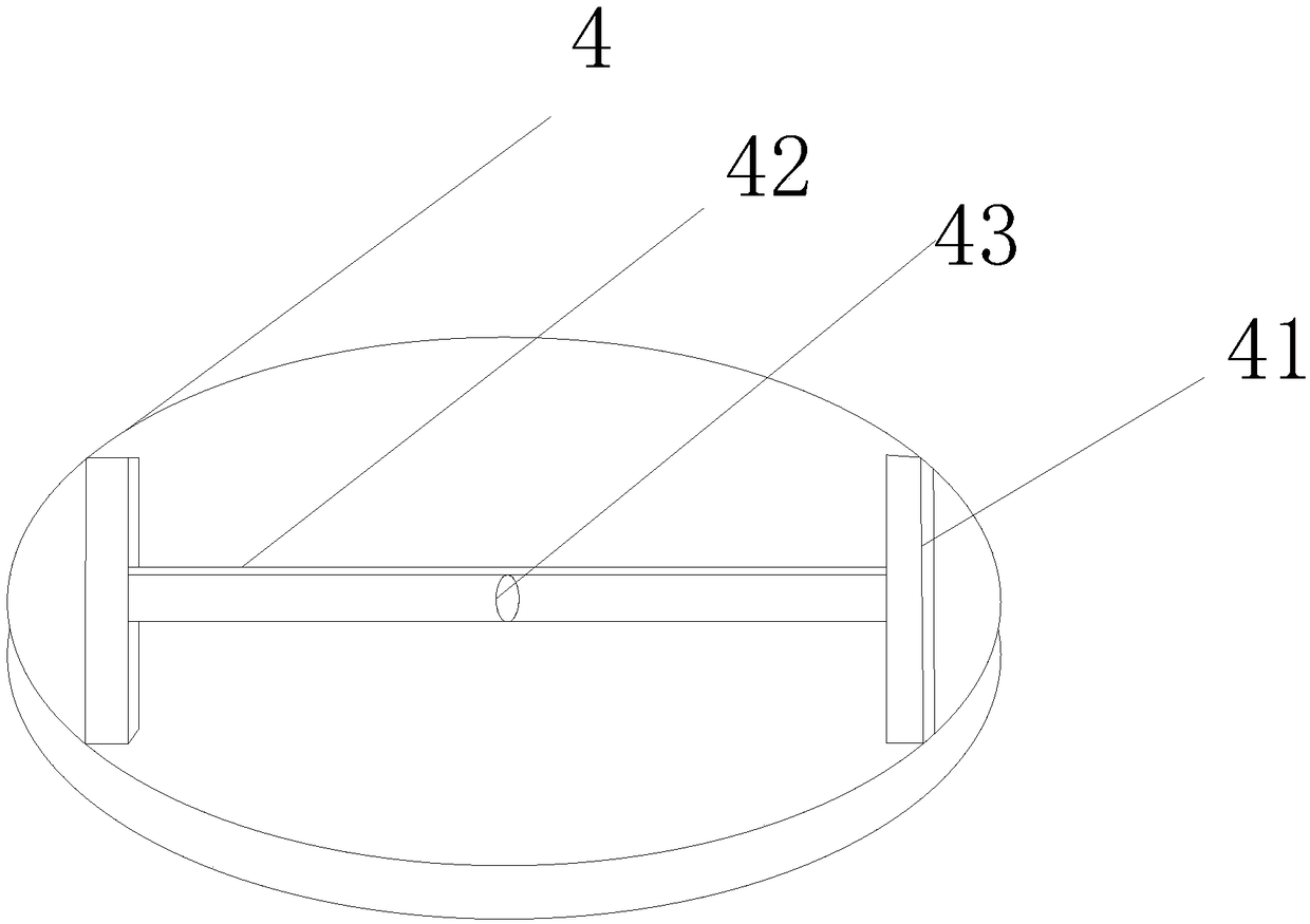
[0017] see Figure 1-2 , the present invention provides a double-layer induction cooker, the structure of which includes a working panel 1, a layer of heating plate 2, a heating coil 3, a composite heating plate 4, a composite drawer 5, an anti-drop bayonet 6, a liquid crystal display panel 7, and a shrinkable panel 8. Gap 9, the working panel 1 is fixedly connected with a layer of heating plate 2, the heating coil 3 is arranged on the layer of heating plate 2, the composite heating plate 4 is arranged under the layer of heating plate 2, and the composite The composite drawer 5 is located below the composite heating plate 4, the gap 9 is fixedly connected with the composite drawer 5, the shrink board 8 is flexibly connected with the composite draw...


PUM


Abstract

The invention provides a double-layer induction cooker, which structurally comprises a work panel, a layer of heating plate, a heating coil, a composite heating plate, a composite drawer, an anti-dropbayonet, a liquid crystal display panel, a retraction plate and a gap, wherein the work panel is fixedly connected with the heating plate; the heating coil is arranged on the heating plate; the composite heating plate is arranged at the lower part of the heating plate; the composite drawer is arranged at the lower part of the composite heating plate; the gap is fixedly connected with the composite drawer; the retraction plate is movably connected with the composite drawer through the gap; the liquid crystal display panel is arranged at the right side of the anti-drop bayonet; the composite heating plate is provided with a magnetic field strip, a conductor and a rotating shaft; the rotating shaft is movably connected with the magnetic field strip; and the conductor is movably connected with the rotating shaft. The double-layer induction cooker is provided with the composite heating plate, so that the double-layer induction cooker has heating and power-saving functions at the same timeand can be more power-saving during double-layer heating.

Description

technical field [0001] The invention is a double-layer electromagnetic cooker, which belongs to the field of electromagnetic cookers. Background technique [0002] Induction cooker is also known as induction cooker. The first household induction cooker was born in Germany in 1957. In 1972, the United States began to produce induction cooker. In the early 1980s, induction cooker began to sell well in Europe, America and Japan. The alternating current passes through the coil to generate an alternating magnetic field whose direction is constantly changing, and eddy currents will appear inside the conductor in the alternating magnetic field, which is caused by the eddy electric field pushing the carriers in the conductor to move; the Joule of eddy current The thermal effect heats up the conductor, thus achieving heating. [0003] The prior art discloses a double-layer induction cooker with application number 201320398943.5. It can overcome the problem that the traditional indu...

Claims


Application Information

Patent Timeline
Patent Type & Authority Applications(China)
IPC IPC(8): H05B6/12H05B6/42F24C7/06F24C7/08
CPCH05B6/12F24C7/067F24C7/086H05B6/42
Inventor 陈永航
Owner 陈永航
Learn More