Non-piercing microwave ablation antenna and application thereof
A microwave ablation and non-puncture technology, which is applied in the fields of application, microwave surgical instruments, and ovulation diagnosis, etc., can solve the problems of difficult to clearly identify GGO, damage blood vessels and bronchi, and difficult to clearly identify GGO, so as to avoid passing through the puncture channel and Bleeding blood vessel spread, good bleeding, prevent lung bleeding effect
- Summary
- Abstract
- Description
- Claims
- Application Information
AI Technical Summary
Problems solved by technology
Method used
Image
Examples
Embodiment 1
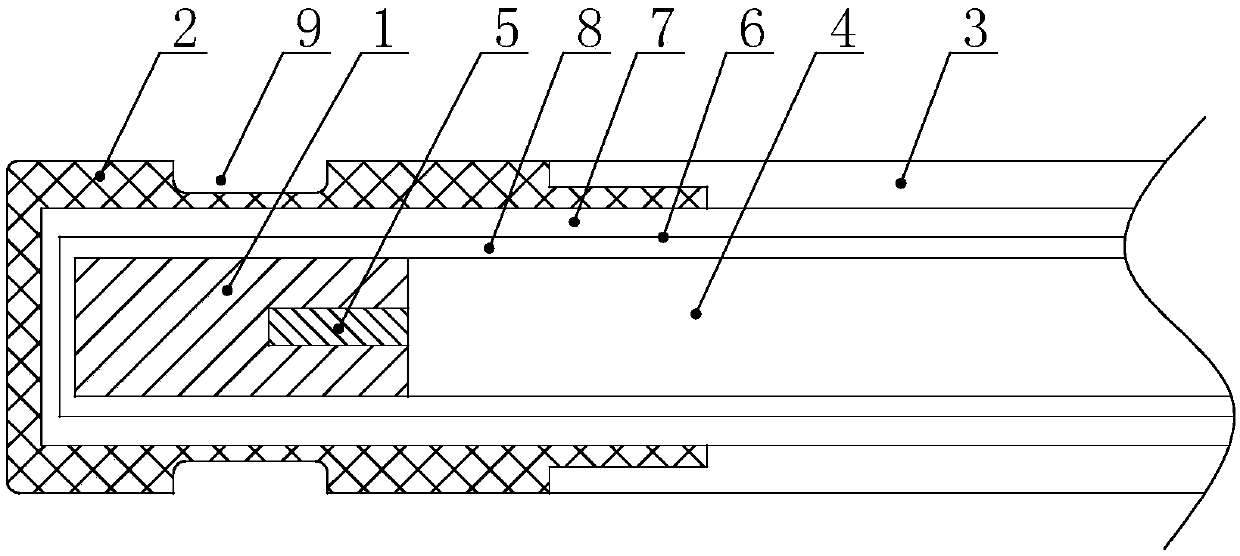
[0020] Such as figure 1 As shown, the non-puncturing microwave ablation antenna in this embodiment has a non-puncturing radiator located at the front end of the antenna, and a radiator cover 2 sheathed on the radiator 1 . The whole radiator cover 2 is made of elastic material. In this example, the radiator cover 2 is made of PI, in addition, it can also be made of polyether ether ketone (PEEK) or zirconium porcelain (non-elastic material). The advantage of using elastic materials is that when the antenna is inserted into the lungs, it will not damage blood vessels or bronchi, and will not cause pulmonary bleeding. Therefore, a better solution is that at least the front end of the radiator cover is made of elastic material, which can meet the design requirements of the present invention. The thickness of the radiator cover is 0.35mm, and the radiator cover is coated with an anti-sticking coating. Of course, since the front end adopts a blunt design (non-puncture type), the r...
Embodiment 2
[0030] Such as Figure 4 As shown, the antenna has a radiator 1 made of metal (the front end of the head is a curved surface), a dielectric sleeve 10 set behind the radiator 1 and a needle bar 3 set at the rear end of the dielectric sleeve 10, and the needle bar 3 runs through A coaxial cable is provided, the rear end of the radiator 1 is connected to the inner conductor 5 of the coaxial cable (conductive connection), and an antenna emission window is formed between the rear end of the radiator 1 and the outer conductor 4 of the coaxial cable. The water diversion pipe 12 is arranged between the coaxial cable and the needle bar 3, and its front end is fixed with the water blocking shaft 11. The gap between the water diversion pipe 12 and the coaxial cable forms a water inlet, and the gap between the water diversion pipe and the needle bar forms a return channel.
[0031] The above-mentioned embodiment lists two shapes of the front end of the radiator (flat head and round head)...
PUM
 Abstract
Description
Claims
Application Information
 - R&D
- Intellectual Property
- Life Sciences
- Materials
- Tech Scout
- Unparalleled Data Quality
- Higher Quality Content
- 60% Fewer Hallucinations
Browse by: Latest US Patents, China's latest patents, Technical Efficacy Thesaurus, Application Domain, Technology Topic, Popular Technical Reports.
© 2025 PatSnap. All rights reserved.Legal|Privacy policy|Modern Slavery Act Transparency Statement|Sitemap|About US| Contact US: help@patsnap.com


