Method for additionally arranging upper wing on flat-plate wing of plate wing machine to improve rigidity and lift force of wing

A board-wing aircraft and wing technology, which is applied in the aviation field, can solve the problems of insufficient rigidity of the wing structure of the board-wing aircraft, divergence of chord blowing airflow, etc., and achieve the effect of eliminating mutual interference, improving structural rigidity and compacting the wing.

Inactive Publication Date: 2018-10-19
KUNMING QIAOYI SCI & TECH CO LTD
View PDF6 Cites 4 Cited by
  • Summary
  • Abstract
  • Description
  • Claims
  • Application Information

AI Technical Summary

Problems solved by technology

[0005] The technical problem to be solved in the present invention is to propose a method for increasing the rigidity and lift of the wing by adding an upper wing on the flat wing of the plate-wing aircraft in order to overcome the insufficient rigidity of the wing structure of the plate-wing aircraft and the divergence of the chord-wise blowing airflow. Make the wing of the plank wing more compact, stable, reasonable and efficient

Method used


Image

  • Method for additionally arranging upper wing on flat-plate wing of plate wing machine to improve rigidity and lift force of wing
  • Method for additionally arranging upper wing on flat-plate wing of plate wing machine to improve rigidity and lift force of wing
  • Method for additionally arranging upper wing on flat-plate wing of plate wing machine to improve rigidity and lift force of wing

Examples


Embodiment 1

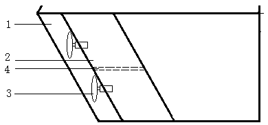
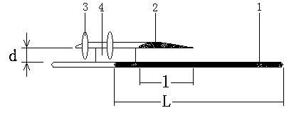
[0025] Embodiment 1: as Figure 1-3As shown, this method of adding an upper wing on the flat wing of a board-wing aircraft to improve wing rigidity and lift is for a small-scale board-wing aircraft that adopts a large-area continuous surface wide-chord wing and chord blowing to realize vertical take-off and landing and flight. , above the flat wing of the plate-wing aircraft (that is, the lower wing), an upper wing with a convex and flat airfoil is set, and the lower wing 1 is used as the main wing and the upper wing 2 is used as the aileron. On the two parallel surfaces of the upper and lower wings Two vertical spoilers 4 are arranged between them to enhance the rigidity, and a rectangular box is surrounded by two adjacent vertical spoilers, the upper surface of the lower wing and the lower surface of the upper wing, which enhances the structural rigidity of the wing and provides The installation of the drive device is convenient (provide a base for the drive device); arrange...

Embodiment 2

[0028] Example 2: see Figure 1-3 , this method of adding an upper wing on the flat wing of a board-wing aircraft to improve wing rigidity and lift is for a large-scale board-wing aircraft that uses a large-area continuous surface wide-chord wing and chord-wise air blowing to achieve vertical take-off and landing and flight. The top of the flat wing (lower wing) of the plate-wing aircraft is provided with an upper wing with a convex upper wing and a lower flat wing, which enhances the structural rigidity of the wing and facilitates the installation of the drive device (provides a base for the drive device to install), and the lower wing 1 is used as the main wing, and the upper wing 2 is used as the aileron. Four vertical spoilers 4 are arranged between the two parallel surfaces of the upper and lower wings to enhance the rigidity. Two adjacent vertical spoilers and the upper wing of the lower wing The surface and the lower surface of the upper wing form a rectangular box; 10 ...

Embodiment 3

[0031] Embodiment 3: see Figure 1-3 , see Figure 1-3 , the method of adding an upper wing on the flat wing of a board-wing aircraft to improve wing rigidity and lift is for a medium-sized board-wing aircraft that uses a large-area continuous surface wide-chord wing and chord-wise air blowing to achieve vertical take-off and landing and flight. The upper wing of the flat-winged wing (that is, the lower wing) is set on the upper side of the flat wing of the plate-wing aircraft. The lower wing 1 is used as the main wing and the upper wing 2 is used as the aileron. Between the two parallel surfaces of the upper and lower wings Three vertical spoilers 4 are set to enhance rigidity, and a rectangular box is surrounded by two adjacent vertical spoilers, the upper surface of the lower wing and the lower surface of the upper wing, which enhances the structural rigidity of the wing and provides The installation of the device is convenient (provide a base for the drive device); 6 smal...


PUM


Abstract

The invention discloses a method for additionally arranging an upper wing on a flat-plate wing of a plate wing machine to improve rigidity and lift force of the wing and belongs to the technical fieldof aviation. The flat-plate wing of the plate wing machine serves as a lower wing, the upper wing in an upper-protruding and lower-flat wing section is arranged above the lower wing, multiple drive devices are arranged on the middle portion of the front edge of the upper wing, the height distance between the upper wing and the lower wing is controlled to be slightly larger than the radius of a propeller of each drive device or the radius of each air injection hole, high-speed air streams are blown in the chordwise direction through the drive devices and evenly divided to the upper surface andthe lower surface of the upper wing, wing lift force is generated through the flow speed difference of the air flowing through the upper surface and the lower surface of the lower wing and the flow speed difference of the air flowing through the upper surface and the lower surface of the upper wing, the lift force of an aircraft can be improved through superposition of the action of the two flowspeed differences, the air stream downwash action of the upper wing is used for forcing the high-speed air streams to be further attached to the upper surface of the lower wing, efficiency is furtherimproved, and the lift force is further increased. The method has the beneficial effects of being capable of bringing the flight efficiency of the upper wing and the lower wing into full play, reasonable in structure, reliable in work, safe, stable, low in cost, high in flight efficiency and the like.

Description

technical field [0001] The invention relates to a method for realizing vertical take-off, landing and flight of an aircraft, in particular to a method for adding an upper wing to a flat wing of a board-wing aircraft to improve the rigidity and lift of the wing, which belongs to the field of aviation technology. Background technique [0002] Manned aircraft can be divided into two categories: fixed wing and rotary wing. Fixed wing is commonly used in horizontal take-off and landing aircraft (such as jet airliners), while rotary wing is commonly used in vertical take-off and landing aircraft (such as helicopters). As far as the current technical level is concerned, fixed-wing aircraft can fly at high speed and are easy to operate, but they need to rely on runways to take off and land. Rotary wing aircraft can take off and land vertically without relying on runways, and has strong adaptability, but the mechanism is out of balance, the control is complicated, the flight speed is...

Claims


Application Information

Patent Timeline
Patent Type & Authority Applications(China)
IPC IPC(8): B64C3/10B64C3/36B64C3/58
CPCB64C3/10B64C3/36B64C3/58
Inventor 杨卫华
Owner KUNMING QIAOYI SCI & TECH CO LTD
Why Eureka
Try Eureka