Main engine for oil drilling machine hydraulic hoister

A hydraulic lifting and drilling rig technology, which is applied in the direction of drill pipes, drill pipes, drilling equipment, etc., can solve problems such as wire rope and pulley wear, heavy objects suspended in the air, and wire rope deflection angles, etc., to improve pressure stability, The effect of uniform span and improved life

Pending Publication Date: 2018-10-19
廖恒伟
View PDF11 Cites 2 Cited by
  • Summary
  • Abstract
  • Description
  • Claims
  • Application Information

AI Technical Summary

Problems solved by technology

The main frame of the existing hydraulic hoist has the following disadvantages: 1) The wire rope deflection angle between the pulley blocks of the hoist main frame is relatively large, and the wire rope and the pulley are severely worn; When the situation cannot be recovered for a short time, the heavy objects hoisted by the hoist are suspended in the air, and it is difficult to lower them, posing a safety hazard

Method used


Image

  • Main engine for oil drilling machine hydraulic hoister
  • Main engine for oil drilling machine hydraulic hoister
  • Main engine for oil drilling machine hydraulic hoister

Examples


Embodiment Construction

[0018] The following will clearly and completely describe the technical solutions in the embodiments of the present invention with reference to the accompanying drawings in the embodiments of the present invention. Obviously, the described embodiments are only some, not all, embodiments of the present invention. Based on the embodiments of the present invention, all other embodiments obtained by persons of ordinary skill in the art without making creative efforts belong to the protection scope of the present invention.

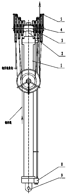
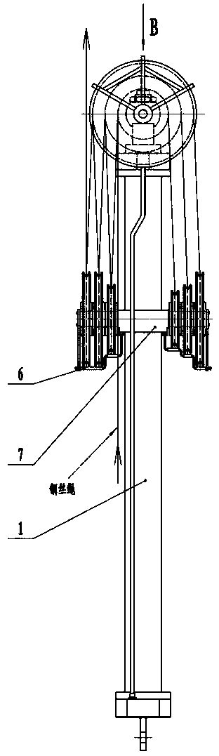
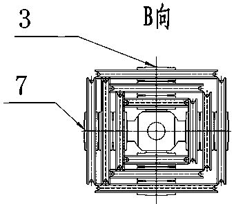
[0019] see Figure 1-4 , the present invention provides a technical solution: a main engine for a hydraulic hoist of an oil drilling rig, including a hydraulic cylinder body 1, a hydraulic cylinder piston rod 2, a movable pulley block 3, a lock nut 4, an upper rope cover 5, a lower rope Cover 6, static pulley block 7, hydraulic valve block 8 and single ear plate 9.

[0020] The outer wall of the hydraulic cylinder body 1 is provided with a static pulley block...


PUM


Abstract

The invention discloses a main engine for an oil drilling machine hydraulic hoister. The engine comprises a hydraulic cylinder body and a hydraulic cylinder piston rod, the outer wall of the hydrauliccylinder body is provided with a fixed pulley block, the outer side of the fixed pulley block is provided with a lower retaining rope cover, the top end of the hydraulic cylinder piston rod is provided with a movable pulley block, the outer side of the movable pulley block is provided with an upper retaining rope cover, the top of the movable pulley block is provided with a locknut, the lower portion of the hydraulic cylinder body is provided with a hydraulic valve block, and the bottom end of the hydraulic cylinder body is provided with a single ear plate. The main engine is provided with the movable and fixed pulley blocks, the central axis of the movable pulley block and the central axis of the fixed pulley block are perpendicular to each other, the movable pulley block and the fixed pulley block are respectively provided with pulleys of different diameters, so that the span is uniform when a steel wire rope penetrates through the pulleys, it is ensured that the deflection angle ofthe steel wire rope is reduced, the eccentric wear is effectively reduced, and the service life of the pulleys and the steel wire rope is prolonged.

Description

technical field [0001] The invention relates to the technical field of oil drilling, in particular to a main engine for an oil drilling rig hydraulic hoist. Background technique [0002] In oil field drilling operations, it is often necessary to carry out hoisting operations such as throwing drilling tools, lifting drilling tools, and transporting objects to the derrick at high altitude. The current common practice is to use tools such as pneumatic winches and hydraulic hoists for lifting operations. The hydraulic hoist is favored by people because of its stable transmission, high efficiency, convenient operation, and the absence of irregular winding of the wire rope of the wind winch. The existing main engine of the hydraulic hoist has the following disadvantages: 1) The wire rope deflection angle between the pulley blocks of the main hoist is relatively large, and the wire rope and the pulley are severely worn; When the situation cannot be recovered for a short time, the...

Claims


Application Information

Patent Timeline
Patent Type & Authority Applications(China)
IPC IPC(8): E21B19/00E21B19/02
CPCE21B19/00E21B19/02
Inventor 廖恒伟
Owner 廖恒伟
Why Eureka
Try Eureka