Ion fan with self-cleaning function

An ion fan, self-cleaning technology, applied in cleaning methods and utensils, cleaning methods using gas flow, components of pumping devices for elastic fluids, etc. Noise and other problems, to achieve the effect of easy miniaturization, low energy consumption, and improved efficiency

Active Publication Date: 2018-10-19
ZHEJIANG UNIV
View PDF9 Cites 6 Cited by
  • Summary
  • Abstract
  • Description
  • Claims
  • Application Information

AI Technical Summary

Problems solved by technology

[0004] The above patents can realize the dust removal of the ion fan, but some methods introduce vibration and noise, and other methods make the system m

Method used


Image

  • Ion fan with self-cleaning function
  • Ion fan with self-cleaning function
  • Ion fan with self-cleaning function

Examples


Embodiment 1

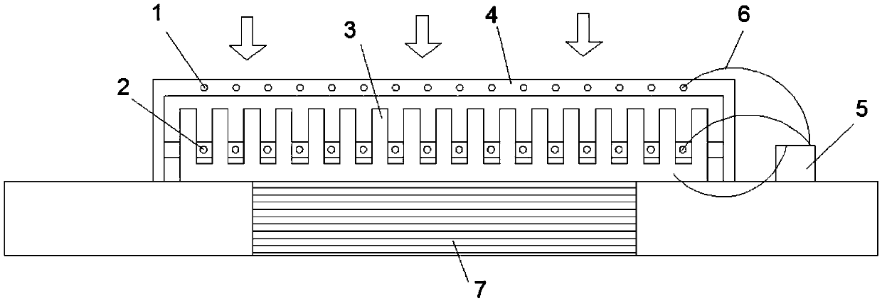
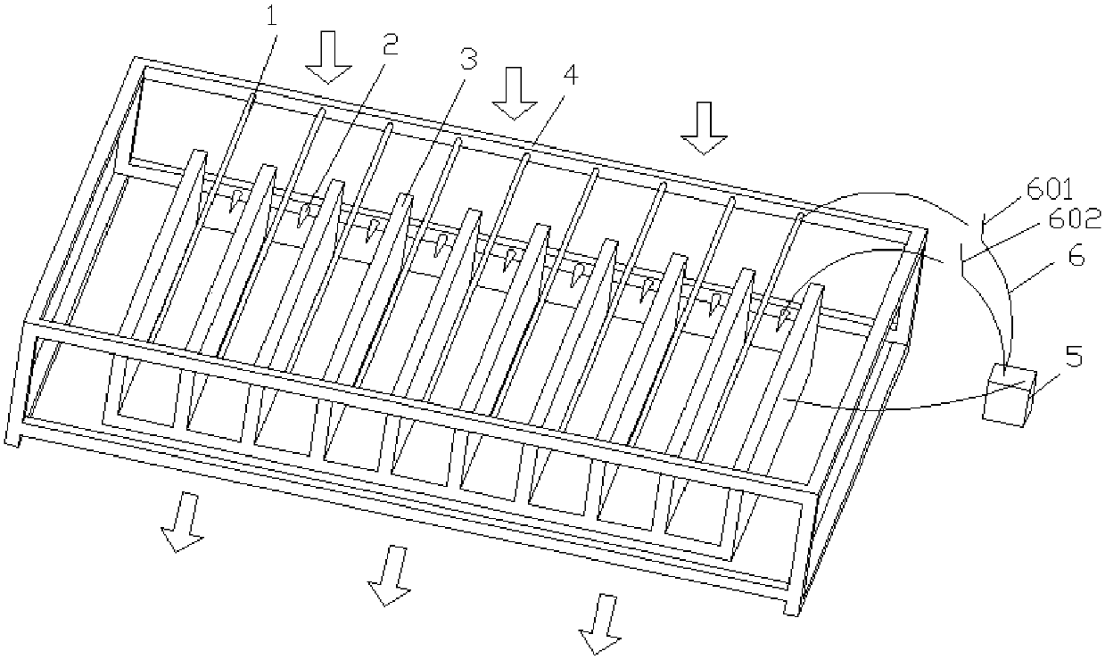
[0029] Such as figure 1 As shown, the heat dissipation system of this embodiment is composed of a heating element 7 and an ion fan with a self-cleaning function. The ion fan with self-cleaning function mainly includes: a discharge electrode 1 for heat dissipation, a discharge electrode 2 for self-cleaning, a collector electrode 3, an electrode frame 4, a driving power supply 5 and a wire 6. Such as figure 2 As shown, the wire 6 includes a cooling circuit switch 601 and a self-cleaning circuit switch 602 .

[0030] In this embodiment, the flat surface of the collecting electrode 3 is close to the heating element, and the opposite surface is a long straight fin structure, and ion wind channels are formed between adjacent fins. The discharge electrode 1 for heat dissipation is a wire electrode, using stainless steel wire, each wire electrode is located above the center line of the two fins, fixed on the electrode frame 4, and connected to the positive pole of the driving power...

Embodiment 2

[0035] The cooling system of this embodiment is the same as that of Embodiment 1 except for the structure of the ion fan with self-cleaning function.

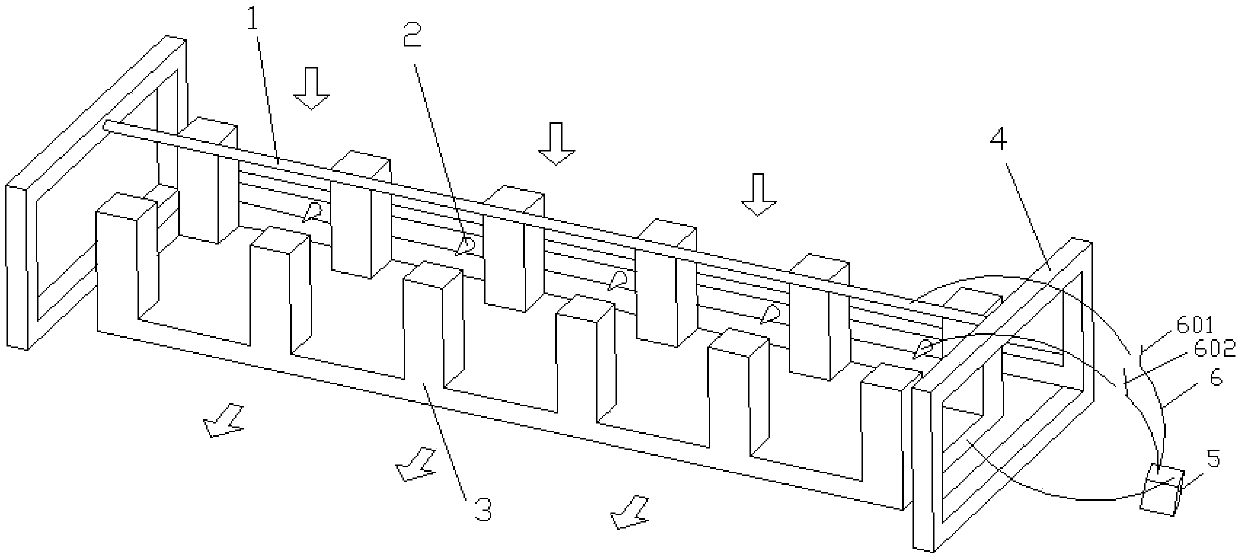
[0036] Such as image 3 As shown, in the ion fan with self-cleaning function in this embodiment, the flat surface of the collector electrode 3 is in contact with the heating element, and the opposite side is composed of fin columns arranged at intervals along the longitudinal direction, and the fin columns are formed in a horizontal direction. ionic wind channel. The discharge electrode 1 for heat dissipation is a linear electrode, made of stainless steel wire, located above the ion wind channel, fixed on the electrode frame 4, and connected to the positive pole of the driving power supply 5 through a lead 6. The self-cleaning discharge electrode 2 is a needle-shaped electrode, near the root of the collector electrode 3 fins, on the electrode frame 4 on the side of the collector electrode 3 ion wind passage, the needle is faci...

Embodiment 3

[0040] The cooling system of this embodiment is the same as that of Embodiment 1 except for the structure of the ion fan with self-cleaning function.

[0041] Such as Figure 4As shown, the flat surface of the collector electrode 3 in this embodiment is in contact with the heating element, and the opposite surface is composed of fin columns arranged at intervals in the longitudinal direction, and ion wind channels extending in the transverse direction are formed between the fin columns. The discharge electrode 1 for heat dissipation is a needle-shaped electrode, located above the ion wind channel, fixed on the electrode frame 4, the needle points to the surface of the collector electrode 3, and is connected to the positive pole of the driving power supply 5 through a wire 6. The self-cleaning discharge electrode 2 is also a needle-shaped electrode, which is located near the root of the collector electrode 3 fins, on the electrode frame 4 on one side of the collector electrode ...


PUM


Abstract

The invention discloses an ion fan with a self-cleaning function, which comprises a collecting electrode, a discharge electrode for heat dissipation, a discharge electrode for self-cleaning and an electrode frame. The collecting electrode comprises a substrate that is in contact with a heating element, and fins arranged at equal intervals on the substrate, wherein an ion wind channel is formed between the fins. The discharge electrode for heat dissipation is fixed to the electrode frame above the ion wind channel, and the discharge electrode for self-cleaning is located on the electrode framelocated on one side of the ion wind channel. The collecting electrode, the discharge electrode for heat dissipation and the discharge electrode for self-cleaning are connected with a power supply viawires, and the discharge electrode for heat dissipation and the discharge electrode for self-cleaning are controlled independently by switches. The ion fan is simple in the system structure, free of vibration noise, low in energy consumption and capable of better exerting the inherent advantages of the ion fan.

Description

technical field [0001] The invention relates to the field of heat dissipation, in particular to an ion fan with self-cleaning function. Background technique [0002] Ionic fans have the advantages of small size, no noise and vibration, and easy adjustment of shape, and have been more and more researched in the field of heat dissipation. However, during the operation of the ion fan, dust in the air will accumulate on the collector and discharge electrodes, and the dust accumulation will reduce the heat dissipation performance of the ion fan. Therefore, it is extremely important to remove the dust on the ion fan in time. [0003] The U.S. Patent No. 4318718 discloses an ion fan that uses a nozzle to remove dust, and the nozzle ejects high-speed flowing gas to remove dust on the discharge electrode. The U.S. Patent No. 6868242 discloses a mechanical dedusting method in which the discharge electrode of the ion fan stretches into the aperture of the band cleaning pad, and remov...

Claims


Application Information

Patent Timeline
IPC IPC(8): F04D29/70F04D25/08F04D27/00B08B5/02
CPCB08B5/02F04D25/08F04D27/008F04D29/703
Inventor 何一坚陈香玉郑舒鹏陈光明孔家煊
Owner ZHEJIANG UNIV
Why Eureka
Try Eureka