Right-angle output steel ball speed reducer

A reducer and steel ball technology, applied in mechanical equipment, transmission parts, friction transmission and other directions, can solve the problems of low service life, low transmission efficiency and complex manufacturing process of the soft tooth surface reducer, and achieve the purpose of solving the problems of soft tooth surface reducer. Low surface strength, short life, improved bearing capacity and service life, and the effect of solving the difficulty of adjusting axial clearance

Pending Publication Date: 2018-10-19
关云龙
View PDF9 Cites 2 Cited by
  • Summary
  • Abstract
  • Description
  • Claims
  • Application Information

AI Technical Summary

Problems solved by technology

But worm gear reducer: the most widely used and the lowest cost, the defect is low transmission accuracy, low rotation accuracy, generally around 20-30 arc minutes, and generally large in size
Low transmission efficiency usually only about 60%
Because it is a soft tooth surface reducer, its service life is low, it is not resistant to impact, and its rigidity is poor compared with metal parts.
[0004] Double-lead worm gear reducer: high transmission precision, but the disadvantage is that the manufacturing process is complicated, the transmission efficiency is low, only about 60%, and the cost is high, because the reducer with soft tooth surface has low service life
[0005] Hyp

Method used


Image

  • Right-angle output steel ball speed reducer
  • Right-angle output steel ball speed reducer
  • Right-angle output steel ball speed reducer

Examples


Embodiment Construction

[0030] The following will clearly and completely describe the technical solutions in the embodiments of the present invention with reference to the accompanying drawings in the embodiments of the present invention. Obviously, the described embodiments are only some, not all, embodiments of the present invention.

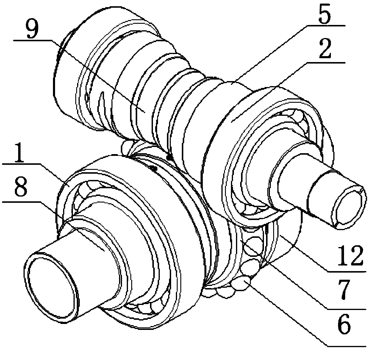
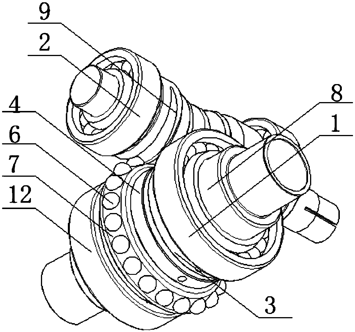
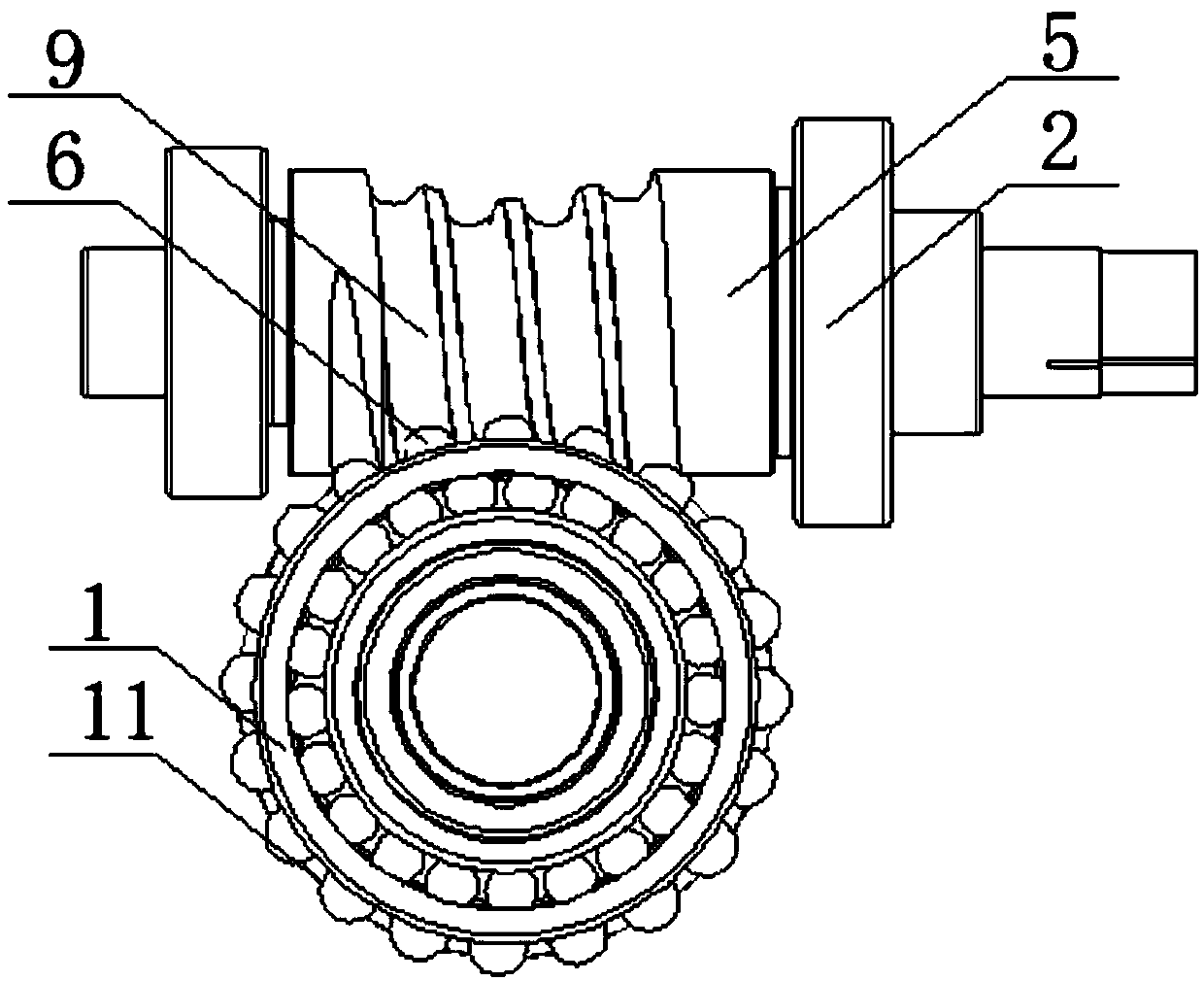
[0031] refer to Figure 1-6 , a right-angle output steel ball reducer, including an input shaft 5 and an output shaft 8, input shaft support bearings 2 are installed at both ends of the input shaft 5, the input shaft support bearings 2 improve the output of the input shaft 5, and the input shaft 5 A plurality of steel ball slides 9 are arranged at equal intervals in the middle, and the steel ball slides 9 are processed in a special way, and the steel ball slides 9 are located between the two input shaft support bearings 2, and the rotation of the input shaft 5 will make the steel ball slides 9 rotation, the two ends of the output shaft 8 are respectively fixed with t...


PUM


Abstract

The invention discloses a right-angle output steel ball speed reducer. The right-angle output steel ball speed reducer comprises an input shaft and an output shaft; input shaft supporting bearings arearranged at the two ends of the input shaft; a plurality of steel ball slideways are arranged on the middle part of the input shaft at equal distance and are positioned between the two input shaft supporting bearings; a first output shaft supporting bearing and a second output shaft supporting bearing are fixed at the two ends of the output shaft correspondingly; a steel ball base output disk isarranged and fixed on the output shaft; and steel balls are arranged in the ball base. The workpieces of the invention are made of high-strength alloy steel and tungsten steel, the problem that the existing right-angle output steel ball speed reducer has low soft tooth surface strength and short life is solved, the service life is prolonged, the engaged gap adopts adjustable design, and the problem of unstable precision caused by processing error is solved. By the transmission mode, the precision of the speed reducer is greatly improved, the demand on high-precision transmission speed reducersin China is met, foreign monopoly is broken, and the right-angle output steel ball speed reducer is convenient to use.

Description

technical field [0001] The invention relates to the technical field of reducers, in particular to a right-angle output steel ball reducer. Background technique [0002] The reducer is generally used for low-speed and high-torque transmission equipment. The motor, internal combustion engine or other high-speed running power is used to achieve the purpose of deceleration through the gear with a small number of teeth on the input shaft of the reducer and the large gear on the output shaft. Ordinary The reducer will also have several pairs of gears with the same principle to achieve the ideal deceleration effect. The ratio of the number of teeth of the large and small gears is the transmission ratio. The function of the reducer is to reduce the speed and increase the output torque at the same time. At the same time, the inertia of the load is reduced, and the reduction of the inertia is the square of the reduction ratio. However, due to the demand for domestic technology and eq...

Claims


Application Information

Patent Timeline
IPC IPC(8): F16H13/04F16H57/12F16H57/022
CPCF16H13/04F16H57/12F16H2057/0221
Inventor 关云龙
Owner 关云龙
Why Eureka
Try Eureka