Spherical involute straight-tooth bevel gear pair and tooth profile modification method thereof

A spherical involute, straight-toothed bevel gear technology, applied in the direction of belts/chains/gears, components with teeth, portable lifting devices, etc., can solve problems such as insufficient modification, modeling method errors, excessive modification, etc. , to achieve the effect of improving meshing quality and service life, reducing vibration and noise

Active Publication Date: 2018-10-19
JIANGSU PACIFIC GEAR DRIVE CO LTD +1
View PDF5 Cites 9 Cited by
  • Summary
  • Abstract
  • Description
  • Claims
  • Application Information

AI Technical Summary

Problems solved by technology

[0002] The transmission ratio change during gear meshing is considered to be one of the sources of gear vibration and noise. In order to ensure a constant transmission ratio, the tooth profile curve of the spur bevel gear pair should be a spherical involute; however, due to the transmission characteristics of the spherical involute I don’t know much about it. Straight bevel gears are generally modeled with back cone involutes. Although the back cone involute is very close to the spherical involute and the modeling is convenient, there are always errors in this modeling method. When the spherical radius The smaller the ratio to the gear modulus, the greater the error; the smaller the ratio of the spherical radius to the gear modulus of the straight bevel gear in a car differential, the greater the tooth profile error, and the resulting change in transmission ratio The vibration and noise caused will be obvious; at present, although the batch forging of spherical involute bevel gears for differentials has not yet been realized, the transmission of spheric

Method used


Image

  • Spherical involute straight-tooth bevel gear pair and tooth profile modification method thereof
  • Spherical involute straight-tooth bevel gear pair and tooth profile modification method thereof
  • Spherical involute straight-tooth bevel gear pair and tooth profile modification method thereof

Examples


Embodiment 1

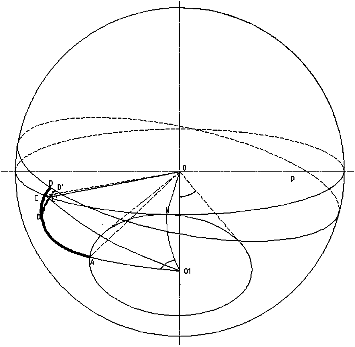
[0064] Such as figure 2 Shown: Section AD is the theoretical spherical involute, plane P is the occurrence surface of the spherical involute, cone OO1A is the base cone of the spherical involute, O is the apex, B is the starting point of the modification, and the tooth profile after modification Divided into two sections, the AB section is the theoretical spherical involute, and the BD' section is the spherical modification curve;

[0065] Establish a global Cartesian coordinate system S, where the origin of the coordinates is the vertex O of the base cone, define the direction of the vector OO1 as the z-axis, define the direction of the vector O1A as the x-axis, and define the directions of the z-axis and the x-axis as y according to the right-hand rule Axis, spherical involute derivation is common knowledge, this application does not make specific derivation, and directly gives the conclusion:

[0066] The spherical involute of segment AB, its equation is:

[0067]

[...

Embodiment 2

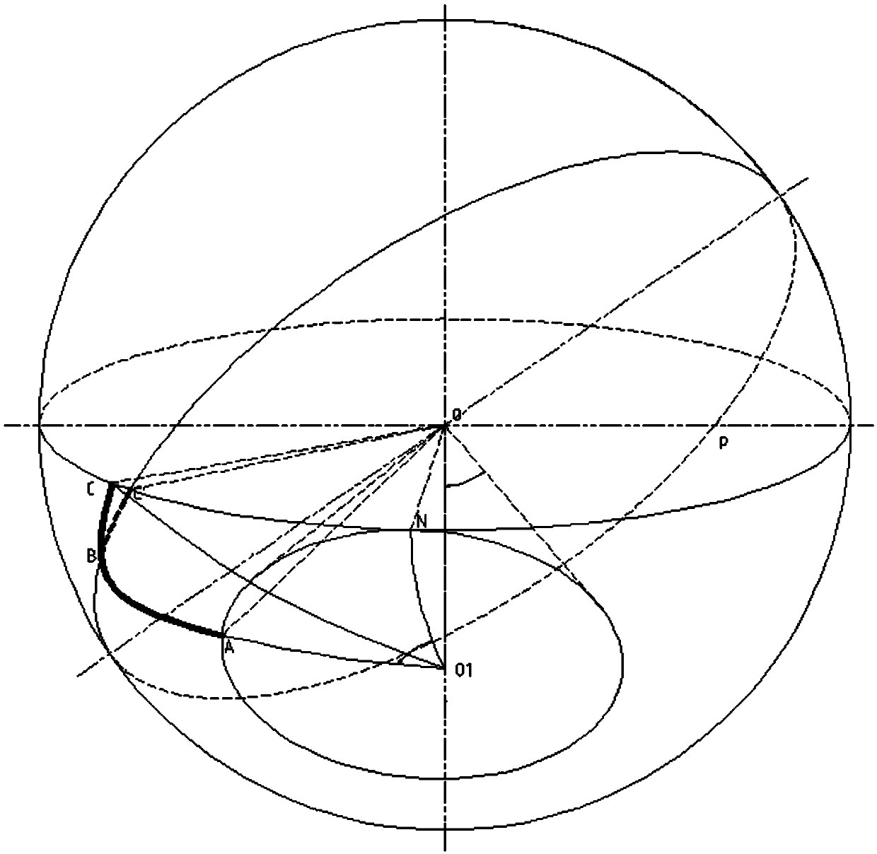
[0107] Such as image 3 As shown, considering that the small end modulus and tooth height of the bevel gear are small, the BC arc length of the part of the spherical involute that needs to be modified here usually does not exceed 0.1, as shown in image 3 The calculation of the method can completely achieve the same technical effect, and can simplify the calculation and improve the work efficiency. In order to simplify the modeling, only the theoretical spherical involute tooth apex C is calculated according to the method in the specific embodiment 1. The coordinate point C' after the tooth top modification , the modification curve BC′ is a section of a great circle inferior arc connecting the tooth tip modification point C′ and the modification starting point B on the spherical surface of the sphere where the spherical involute is located; its equation is easy to obtain, and the three-dimensional modeling is also extremely convenient; Fig. Among them, segment AC is the theore...


PUM


Abstract

The invention discloses a spherical involute straight-tooth bevel gear pair and a tooth profile modification method thereof. The spherical involute straight-tooth bevel gear pair comprises a driving gear and a driven gear, wherein the driving gear meshes with the driven gear, and the tooth profile of each gear is divided into two segments, an AB segment is a theoretical spherical involute, a BD' segment is a spherical surface modification curve, and a B point is the modification starting point. The tooth profile modification method of the gear pair includes the following steps of software modeling, manufacturing of a profile modification mold and mass production. According to the spherical involute straight-tooth bevel gear pair, tooth profile modification of the driving gear and the driven gear adopts the method of tooth top profile modification at the same time; and the profile modification curve is a curve on the spherical surface on which the spherical involute lies, the profile modification direction is the direction of the spherical involute normal line, the profile modification starting point and the profile modification quantity can be optimized and obtained according to the finite element algorithm, the engaging-in and engaging-out impacts of the gears are reduced, vibration and noise are reduced, the meshing quality the gear pair is improved and the service life of the gear pair is prolonged.

Description

technical field [0001] The invention relates to the technical field of gear design and manufacture, in particular to a spherical involute straight bevel gear pair and a tooth profile modification method thereof. Background technique [0002] The transmission ratio change during gear meshing is considered to be one of the sources of gear vibration and noise. In order to ensure a constant transmission ratio, the tooth profile curve of the spur bevel gear pair should be a spherical involute; however, due to the transmission characteristics of the spherical involute I don’t know much about it. Straight bevel gears are generally modeled with back cone involutes. Although the back cone involute is very close to the spherical involute and the modeling is convenient, there are always errors in this modeling method. When the spherical radius The smaller the ratio to the gear modulus, the greater the error; the smaller the ratio of the spherical radius to the gear modulus of the strai...

Claims


Application Information

Patent Timeline
IPC IPC(8): F16H55/17F16H55/08
CPCF16H55/08F16H55/17
Inventor 焦继松王小乾申明许君陈晨张辰瑞王颖
Owner JIANGSU PACIFIC GEAR DRIVE CO LTD
Why Eureka
Try Eureka