
Device and method for calibrating temperature of fiber bragg grating temperature sensor in low-temperature environment

A technology of temperature sensor and optical fiber grating, which is applied in the field of temperature calibration device of optical fiber grating temperature sensor, can solve the problems of large error and low efficiency, achieve uniform cooling and improve calibration efficiency

Active Publication Date: 2018-10-19
富通集团(天津)超导技术应用有限公司
View PDF6 Cites 3 Cited by
  • Summary
  • Abstract
  • Description
  • Claims
  • Application Information

AI Technical Summary

Problems solved by technology

[0004] (1) For the sensitized fiber grating, if the temperature value is directly derived from the theoretical formula without reference calibration, it will lead to large errors in actual use;
[0005] (2) In the process of fiber grating calibration, it needs to go through many times of heating and cooling in the liquid nitrogen temperature zone. Only one fiber grating sensor is calibrated at a time, and the efficiency is low

Method used


Image

  • Device and method for calibrating temperature of fiber bragg grating temperature sensor in low-temperature environment
  • Device and method for calibrating temperature of fiber bragg grating temperature sensor in low-temperature environment
  • Device and method for calibrating temperature of fiber bragg grating temperature sensor in low-temperature environment

Examples


Embodiment Construction

[0030] Embodiments of the device for calibrating a fiber grating temperature sensor in a low temperature environment according to the present invention will be described below with reference to the accompanying drawings. Those skilled in the art would recognize that the described embodiments can be modified in various ways or combinations thereof without departing from the spirit and scope of the invention. Accordingly, the drawings and description are illustrative in nature and not intended to limit the scope of the claims. Also, in this specification, the drawings are not drawn to scale, and like reference numerals denote like parts.

[0031] In the following embodiments, liquid nitrogen is used as the low-temperature medium, but it is not limited to liquid nitrogen, and can also be used for calibration of fiber grating temperature sensors in other low-temperature environments.

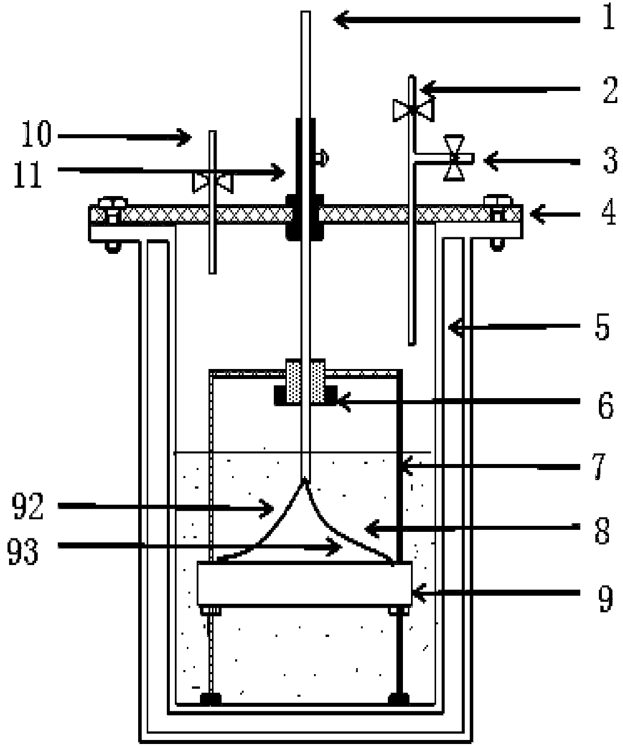
[0032] Such as figure 1 As shown, the fiber grating temperature sensor calibration device in a...


PUM


Abstract

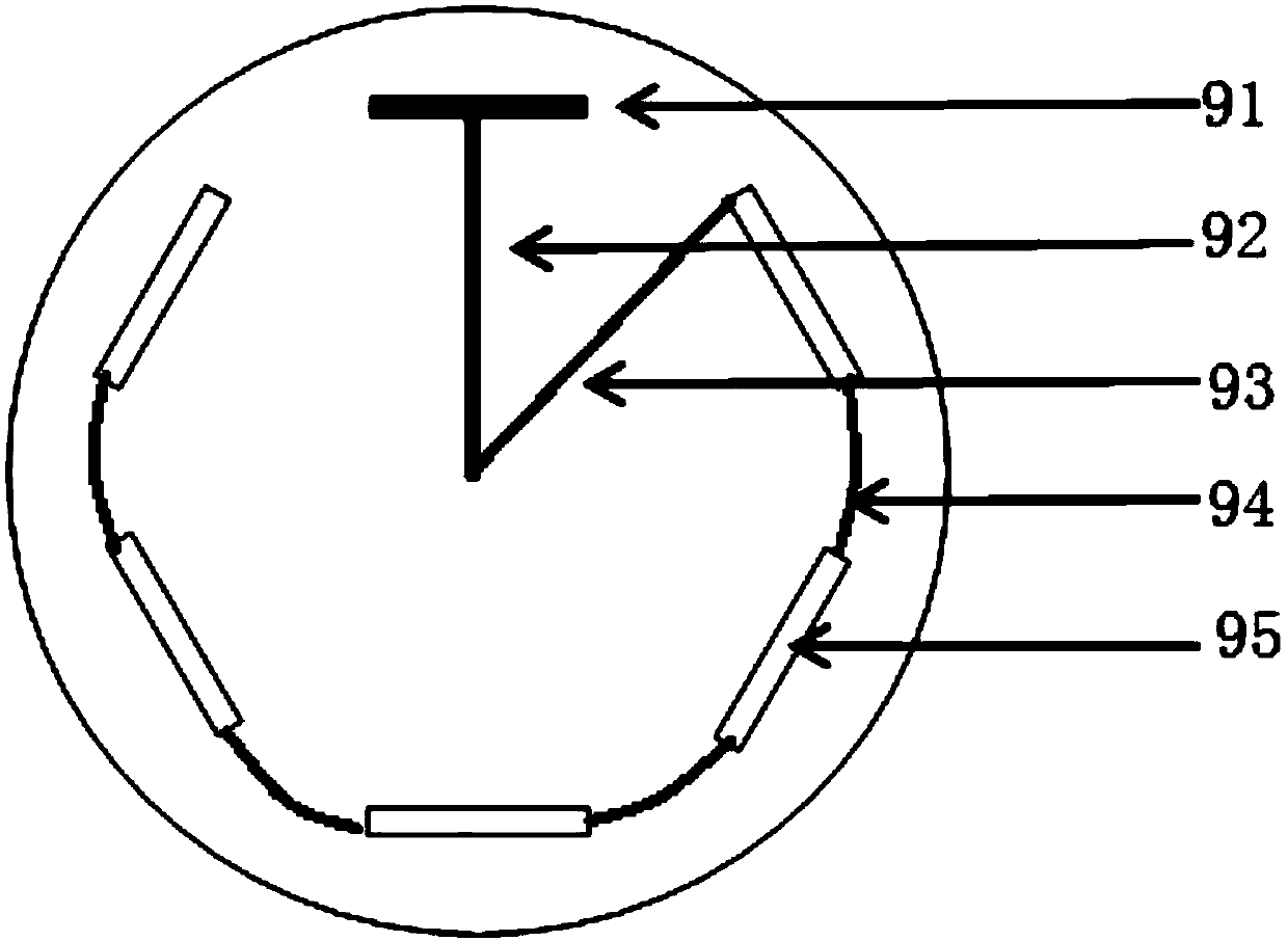
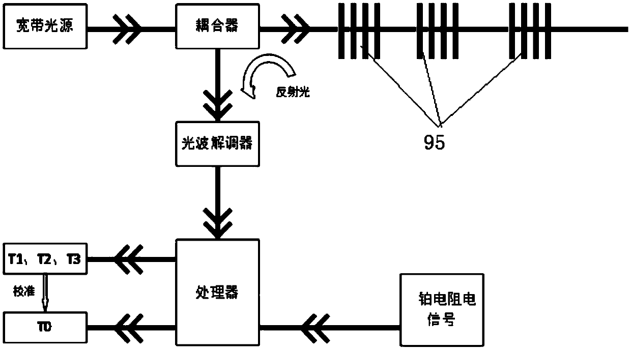
A device and method for calibrating the temperature of a fiber bragg grating temperature sensor in a low-temperature environment are provided. The calibration device comprises a cylinder body, a coverplate, an isothermal block, a lead pipe, a heating block and a calibration module. The upper end of the cylinder body has an opening. The lower end of the cylinder body is closed. A low-temperature medium is disposed in the cylinder body. The cover plate is installed at the upper end of the cylinder body and is provided with a liquid inlet for injecting the low-temperature medium, an exhaust portand a vacuum port. The isothermal block is immersed in the low-temperature medium. The isotherm on the isothermal block is provided with a platinum resistor and a plurality of fiber bragg gratings. The fiber bragg grating are connected in series via optical fibers. The lead pipe extends through the cover plate into the cylinder body. The fiber bragg gratings extend out of cylinder body via the lead pipe by the optical fibers. The platinum resistor extends out of cylinder body via the lead pipe by a signal line. The heating block is disposed on the outer wall of the lead pipe. A heating blockpower line is also arranged in the lead pipe. The calibration module is connected with the optical fibers outside the cylinder body and the signal line of the platinum resistor, and obtains the temperature of the platinum resistor and the temperature of respective fiber bragg gratings according to an obtained signal.

Description

technical field [0001] The invention relates to the field of optical fiber technology, in particular to a temperature calibration device and calibration method for an optical fiber grating temperature sensor in a low temperature environment. Background technique [0002] In the field of high-temperature superconducting power, due to strong electromagnetic interference, temperature sensors such as Pt platinum resistors and thermocouples have insufficient measurement accuracy in measuring liquid nitrogen temperature. Fiber Bragg grating sensors, as passive sensors, transmit temperature signals through light and are not subject to electromagnetic interference. At the same time, it has the characteristics of corrosion resistance, small size, light weight, and high measurement accuracy. It is widely used in the normal temperature environment, but in the low temperature liquid nitrogen environment, due to the nonlinear relationship between the thermo-optic coefficient, thermal expa...

Claims


Application Information

Patent Timeline
IPC IPC(8): G01K15/00
CPCG01K15/005
Inventor 朱红亮夏芳敏
Owner 富通集团(天津)超导技术应用有限公司
Learn More