Machine tool cutter washing and maintaining equipment

A cutting tool and machine tool technology, applied in the field of machine tool tool cleaning and maintenance equipment, can solve problems such as low cleaning efficiency, slow processing process, and reduced production efficiency, and achieve the effects of wide market value, huge economic benefits, and simple operation

Inactive Publication Date: 2018-10-23
繁昌县通民机械制造有限公司
View PDF3 Cites 2 Cited by
  • Summary
  • Abstract
  • Description
  • Claims
  • Application Information

AI Technical Summary

Problems solved by technology

[0003] Most production factories use manual cleaning and maintenance for machine tool tools, the cleaning efficiency is low, and it takes a long time to process a large number of tools to be processed produced by production, the cleaning efficiency is low, and there may be incomplete cleaning, which affects the service life of the tool. Long-term shelving of tools requires Artificially applying anti-rust oil, the processing process is slow, which greatly increases the production cost and reduces the production efficiency. Therefore, in view of the above problems, a machine tool tool cleaning and maintenance equipment is proposed

Method used


Image

  • Machine tool cutter washing and maintaining equipment
  • Machine tool cutter washing and maintaining equipment
  • Machine tool cutter washing and maintaining equipment

Examples


Embodiment Construction

[0018] The following will clearly and completely describe the technical solutions in the embodiments of the present invention with reference to the accompanying drawings in the embodiments of the present invention. Obviously, the described embodiments are only some, not all, embodiments of the present invention. Based on the embodiments of the present invention, all other embodiments obtained by persons of ordinary skill in the art without making creative efforts belong to the protection scope of the present invention.

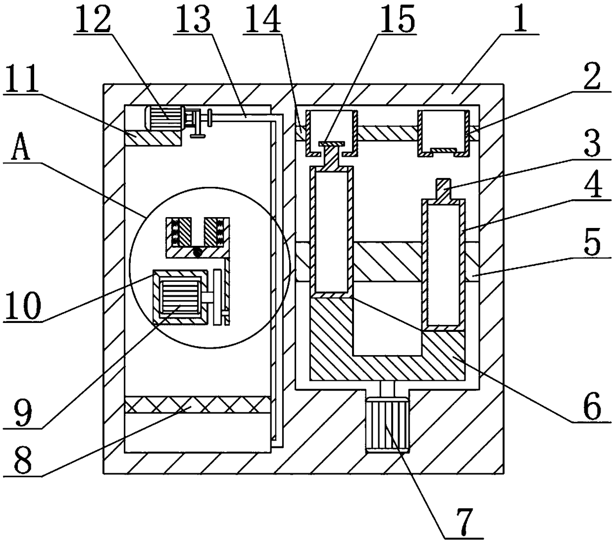
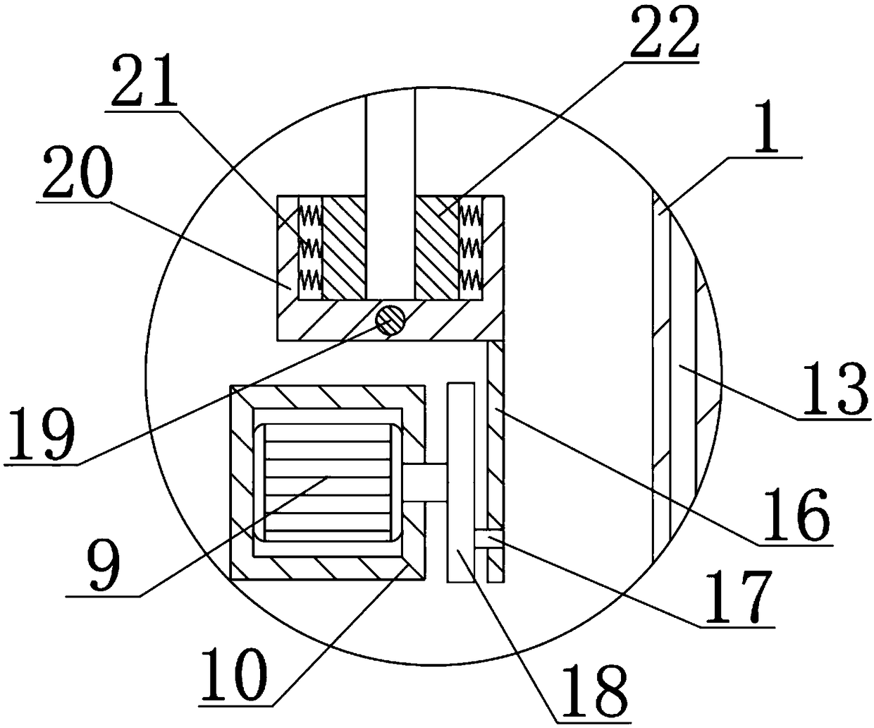
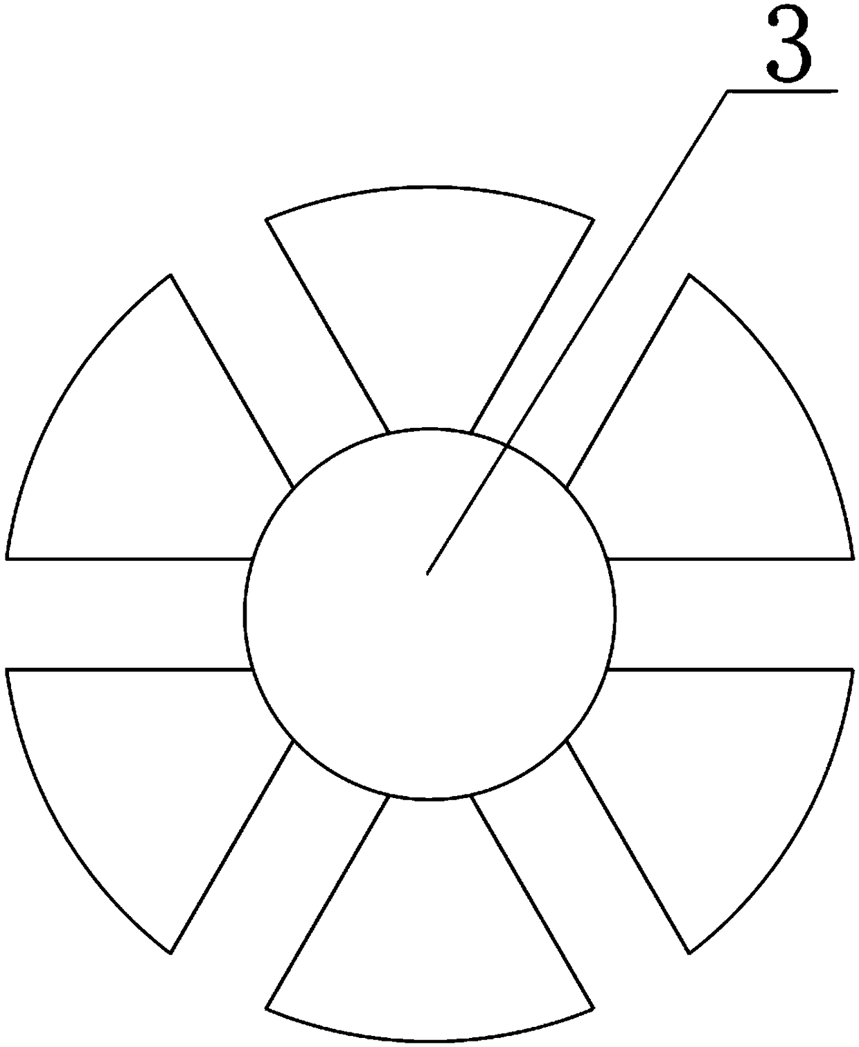
[0019] see Figure 1-3 , the present invention provides a technical solution:

[0020] A machine tool tool cleaning and maintenance equipment, comprising a housing 1, a water pump base 11 is fixedly connected to the upper end of the inner wall on the left side of the housing 1, a water pump 12 is fixedly connected to the upper end of the water pump base 11, and the water inlet on the right side of the water pump 12 is fixed A water pipe 13 is connected, and t...


PUM


Abstract

The invention relates to the technical field of mechanical equipment, in particular to machine tool cutter washing and maintaining equipment. The upper end of the inner wall of the left side of a shell is fixedly connected with a water pump base; the upper end of the water pump base is fixedly connected with a water pump; a water inlet on the right side of the water pump is fixedly connected witha water pipe; the water pipe is connected to the lower end from the upper end of a middle baffle of the shell; the inner wall of the front end of the left side of the shell is fixedly connected with amotor base; the rear end of the motor base is fixedly connected with a second motor; the right end of the second motor is rotationally connected with a rotary wheel; and through arrangement of a rotary table and a check block, the rotation heights of the rotary table are not consistent, when the highest point of the rotary table moves to the position below a container, the container is located atthe highest position, a plug pushes the check block so that oil in an oil tank can evenly flow into the container, a cutter is lubricated, the rotary table rotates continuously, periodic vertical movement of the container is achieved, and the regular maintenance function is achieved. The machine tool cutter washing and maintaining equipment is low in cost, is easy to operate, has great economic benefits and wide market value, and is worthy of application and popularization.

Description

technical field [0001] The invention relates to the technical field of mechanical equipment, in particular to a machine tool tool cleaning and maintenance equipment. Background technique [0002] Machine tool tool cleaning and maintenance equipment is a kind of equipment that can clean most machine tool tools and periodically perform anti-rust maintenance on the tools. Cleaning costs, periodic maintenance to prevent the tool from rusting on the surface for a long time and prolong the service life of the tool. Therefore, the demand for machine tool tool cleaning and maintenance equipment is increasing. [0003] Most production factories use manual cleaning and maintenance for machine tool tools, the cleaning efficiency is low, and it takes a long time to process a large number of tools to be processed produced by production, the cleaning efficiency is low, and there may be incomplete cleaning, which affects the service life of the tool. Long-term shelving of tools requires A...

Claims


Application Information

Patent Timeline
Patent Type & Authority Applications(China)
IPC IPC(8): B08B3/02B08B3/08B08B3/14F16N11/00
CPCB08B3/022B08B3/08B08B3/14F16N11/00
Inventor 不公告发明人
Owner 繁昌县通民机械制造有限公司
Why Eureka
Try Eureka