Paper collecting device

A collection device and paper technology, which is applied in packaging, food packaging, transportation and packaging, etc., can solve the problems that the staff are difficult to find, unfavorable for long-term storage of paper, and unable to be scrapped, so as to improve practicability and functionality and reduce waste. Limited, practical effects

Inactive Publication Date: 2018-10-23
刘以年
View PDF0 Cites 0 Cited by
  • Summary
  • Abstract
  • Description
  • Claims
  • Application Information

AI Technical Summary

Problems solved by technology

[0002] Paper: a thin sheet made of plant fibers, used for painting, printing books, newspapers, packaging, etc. Paper: the general name of paper, paper is counted in sheets, so it is called, paper is generally divided into letterpress printing paper, newsprint, offset printing paper, Coated paper, book cover paper, dictionary paper, copy paper, board paper, etc., because paper is widely used, especially in the office field, it is easy to produce a large amount of paper, but some documents and other contents on some paper are too important to be scrapped. The paper needs to be collected and stored through the corresponding collection device, but the existing paper collection device is relatively lacking, the function is relatively single, and there are many deficiencies when using the operation. The traditional paper collection device is basically a cabinet with a simple structure. Although the purpose of paper collection is achieved, the collection is relatively uniform, and it is difficult for the staff to find it, which reduces the practicability of the device. At the same time, the traditional paper collection device has poor moisture-proof performance, which is not conducive to the long-term preservation of paper. Placement, it is easy to cause mildew and damage to the paper

Method used


Image

  • Paper collecting device
  • Paper collecting device
  • Paper collecting device

Examples


Embodiment Construction

[0014] The following will clearly and completely describe the technical solutions in the embodiments of the present invention with reference to the accompanying drawings in the embodiments of the present invention. Obviously, the described embodiments are only some, not all, embodiments of the present invention. Based on the embodiments of the present invention, all other embodiments obtained by persons of ordinary skill in the art without making creative efforts belong to the protection scope of the present invention.

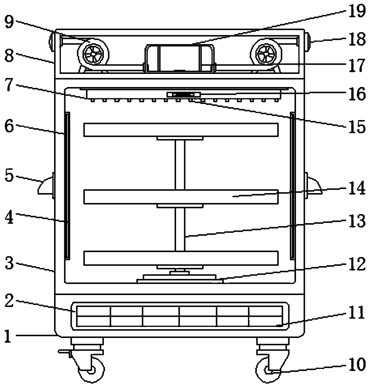
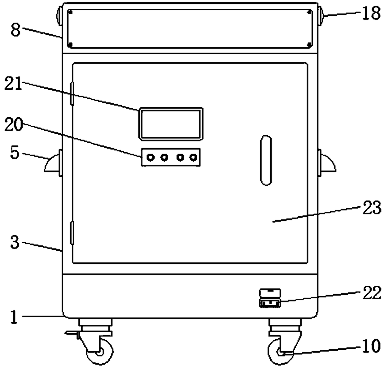
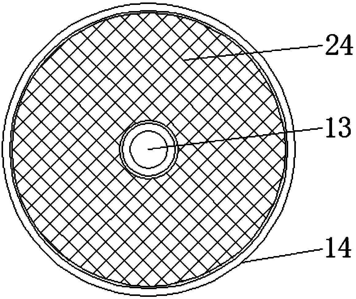
[0015] see Figure 1-3 , an embodiment provided by the present invention: a paper collecting device, including a base 1, a housing 3, an installation chamber 8, a placement box 14 and a second air guide chamber 19, the bottom of the base 1 is equipped with a walking wheel 10, and the walking Braking parts are installed on the wheel 10, and the braking parts can stop the traveling wheels, avoiding the movement of the device during operation, and improving the s...


PUM


Abstract

The invention discloses a paper collecting device comprising a base, a shell, a mounting chamber, three sets of storing boxes and a second air guiding cavity. Travelling wheels are mounted at the bottom of the base. The base is internally provided with a placing groove, and a storage battery is mounted in the placing groove. The shell is mounted at the top of the base. A supporting rod is mountedin the center of the bottom end of the interior of the shell through a rotating disc. The three sets of storing boxes are mounted on the supporting rod at equal intervals, and net plates are mounted on the bottom surfaces of the interiors of the storing boxes. Mounting seats are mounted on the two side walls of the interior of the shell correspondingly, and LED lamp tubes are mounted in the mounting seats. The paper collecting device is composed of a series of structures such as the base, the shell, the mounting chamber, the storing boxes and the second air guiding cavity, the supporting rod can rotate through the rotating disc, different types of paper is conveniently collected through the storing boxes, the interior of the paper collecting device can be ventilated and dried through a draught fan, guided air can be heated by heating resistor wires, practicability is high, and the paper collecting device is worth using and popularizing.

Description

technical field [0001] The invention relates to the field of collecting devices, in particular to a paper collecting device. Background technique [0002] Paper: a thin sheet made of plant fibers, used for painting, printing books, newspapers, packaging, etc. Paper: the general name of paper, paper is counted in sheets, so it is called, paper is generally divided into letterpress printing paper, newsprint, offset printing paper, Coated paper, book cover paper, dictionary paper, copy paper, board paper, etc., because paper is widely used, especially in the office field, it is easy to produce a large amount of paper, but some documents and other contents on some paper are too important to be scrapped. The paper needs to be collected and stored through the corresponding collection device, but the existing paper collection device is relatively lacking, the function is relatively single, and there are many deficiencies when using the operation. The traditional paper collection de...

Claims


Application Information

Patent Timeline
Patent Type & Authority Applications(China)
IPC IPC(8): B65D77/04B65D25/24B65D81/26B65D81/36B65D81/34
CPCB65D77/0446B65D25/24B65D81/261B65D81/3476B65D81/365B65D2577/045
Inventor 刘以年
Owner 刘以年
Why Eureka
Try Eureka