
Yarn lubricating conveying device

A transmission device and yarn technology, which is applied in the directions of transportation and packaging, delivery of filamentous materials, and thin material processing, etc. Avoid problems such as end breaks and burrs, and achieve the effect of avoiding yarn slack

Inactive Publication Date: 2018-10-23
XIANGSHUI YONGTAI TEXTILE GARMENT CO LTD
View PDF0 Cites 9 Cited by
  • Summary
  • Abstract
  • Description
  • Claims
  • Application Information

AI Technical Summary

Problems solved by technology

[0002] Because of its good moisture absorption and air permeability, soft and comfortable to wear, and good warmth retention, the fabric has been widely used in our daily life, and the fabric has good dyeing performance, bright color, complete color spectrum, and strong alkali resistance. Heat and light resistance, especially warp-knitted fabrics, have good elongation and stretchability, and good dimensional stability. Need, it is necessary to use the winding device to wind each small yarn bobbin into a relatively large yarn bobbin, and then place the larger yarn bobbin on the warp knitting machine, so that the service life of the yarn bobbin is improved, ensuring that the warp knitting machine weaves In the process of winding a small yarn bobbin into a large yarn bobbin, the yarn needs to be conveyed. The traditional yarn conveying device cannot conveniently add yarn lubrication during the yarn conveying process. oil, so that the yarn is prone to breakage and burrs, and the fabric made of this yarn is also rough, and it is difficult to achieve soft, smooth and comfortable wearing effects, which cannot meet the needs of production

Method used


Image

  • Yarn lubricating conveying device

Examples


Embodiment Construction

[0018] The following will clearly and completely describe the technical solutions in the embodiments of the present invention with reference to the accompanying drawings in the embodiments of the present invention. Obviously, the described embodiments are only some, not all, embodiments of the present invention.

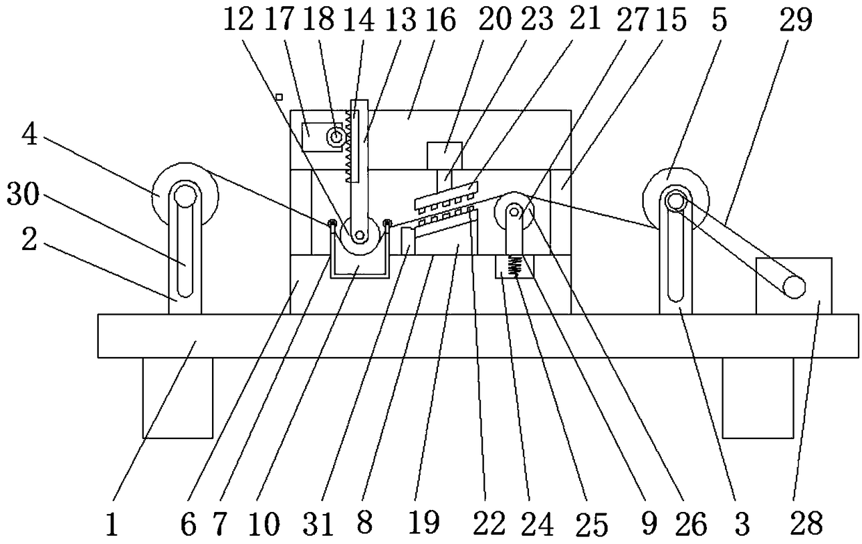
[0019] refer to figure 1 , a kind of yarn lubricating transmission device, comprises workbench 1, and workbench 1 is respectively provided with first support 2 and second support 3, and first support 2 is provided with unwinding roller 4, and second support 3 is provided with Winding roller 5, base 6 is arranged between first support 2 and second support 3, and lubricating mechanism 7, cleaning mechanism 8 and tensioning mechanism 9 are arranged successively on base 6 according to the direction of yarn transmission, and lubricating mechanism 7 comprises The lubricating trough 10, two top line rollers 11 and lubricating roller 12, the two top line rollers 11 are arran...


PUM


Abstract

The invention discloses a yarn lubricating conveying device which comprises a workbench. The workbench is provided with a first support and a second support; the first support is provided with an unwinding roller; the second support is provided with a winding roller; and a base is arranged between the first support and the second support. A lubricating mechanism, a cleaning mechanism and a tensioning mechanism are sequentially arranged on the base in the conveying direction of yarns. The lubricating mechanism comprises a lubricating material groove, two yarn ejecting rollers and lubricating rollers. The cleaning mechanism comprises a benchboard, a second motor and a pressing plate, and cleaning brushes are evenly distributed on the benchboard. The tensioning mechanism comprises a groove, aspring and a transitional roller which are arranged on the base, and a winding motor is arranged on the side, away from the base, of the second support. An output shaft of the winding motor is sleeved with a belt, and the other end of the belt is arranged at one end of the winding roller in a sleeving mode. According to the yarn lubricating conveying device, the yarns can be fully lubricated, redundant lubricants on the yarns can be removed, and the yarns can be more tidy and cleaner in the winding process.

Description

technical field [0001] The invention relates to the technical field of textile equipment, in particular to a yarn lubrication transmission device. Background technique [0002] Because of its good moisture absorption and air permeability, soft and comfortable to wear, and good warmth retention, the fabric has been widely used in our daily life, and the fabric has good dyeing performance, bright color, complete color spectrum, and strong alkali resistance. Heat and light resistance, especially warp-knitted fabrics, have good elongation and stretchability, and good dimensional stability. Need, it is necessary to use the winding device to wind each small yarn bobbin into a relatively large yarn bobbin, and then place the larger yarn bobbin on the warp knitting machine, so that the service life of the yarn bobbin is improved, ensuring that the warp knitting machine weaves In the process of winding a small yarn bobbin into a large yarn bobbin, the yarn needs to be conveyed. The ...

Claims


Application Information

Patent Timeline
IPC IPC(8): B65H71/00
CPCB65H71/007B65H2701/31
Inventor 夏平
Owner XIANGSHUI YONGTAI TEXTILE GARMENT CO LTD
Learn More