
Spacing device and spacing method

A separation device and separation method technology, which is applied in the manufacture of electrical components, circuits, semiconductors/solid devices, etc., can solve the problem of narrowing the distance between adherends and achieve the effect of expanding the distance between them

Pending Publication Date: 2018-10-23
LINTEC CORP
View PDF10 Cites 0 Cited by
  • Summary
  • Abstract
  • Description
  • Claims
  • Application Information

AI Technical Summary

Problems solved by technology

[0006] However, in the conventional separation device described in Patent Document 1, for example, when the sheet-shaped body (adhered body) whose mutual interval is enlarged on the adhesive sheet is conveyed together with the adhesive sheet, when the holding When the holding of the unit to the adhesive sheet disappears, the tension applied to the adhesive sheet is released, and the state closes to the state before deformation, so there is a disadvantage that the mutual interval between the adherends is narrowed

Method used


Image

  • Spacing device and spacing method
  • Spacing device and spacing method
  • Spacing device and spacing method

Examples


Embodiment Construction

[0034] Hereinafter, embodiments of the present invention will be described based on the drawings.

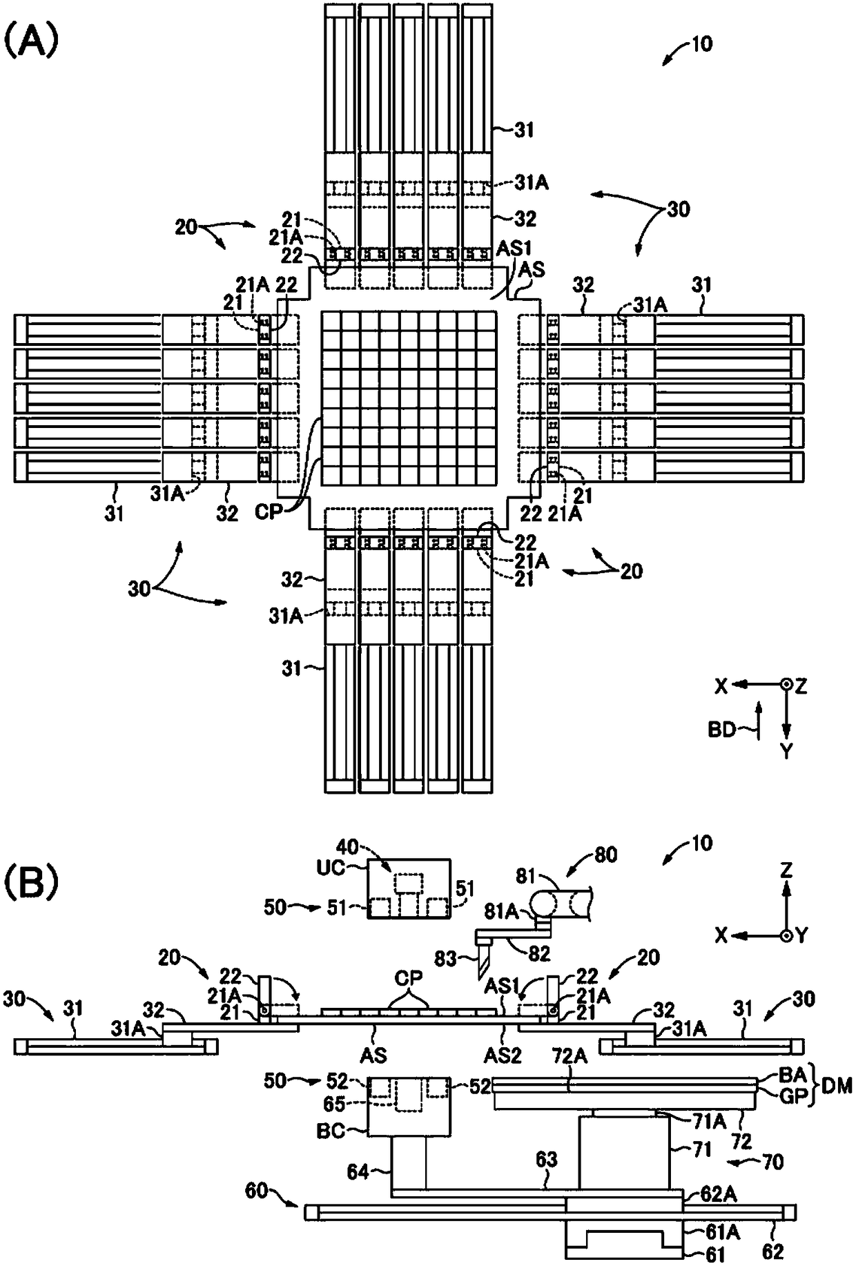
[0035] It should be noted that the X-axis, Y-axis, and Z-axis in this embodiment are in a relationship of being perpendicular to each other, and the X-axis and the Y-axis are axes within a predetermined plane, and the Z-axis is an axis orthogonal to the above-mentioned predetermined plane. Furthermore, in the present embodiment, when viewing from the direction of the arrow BD parallel to the Y-axis as a reference, when the direction is shown without citing a figure constituting a reference, "up" is defined as the direction of the arrow of the Z-axis. , "Down" as its reverse, "Left" as the arrow direction of the X-axis, "Right" as its reverse, "Front" as the arrow direction of the Y-axis, and "Back" as its reverse Towards.

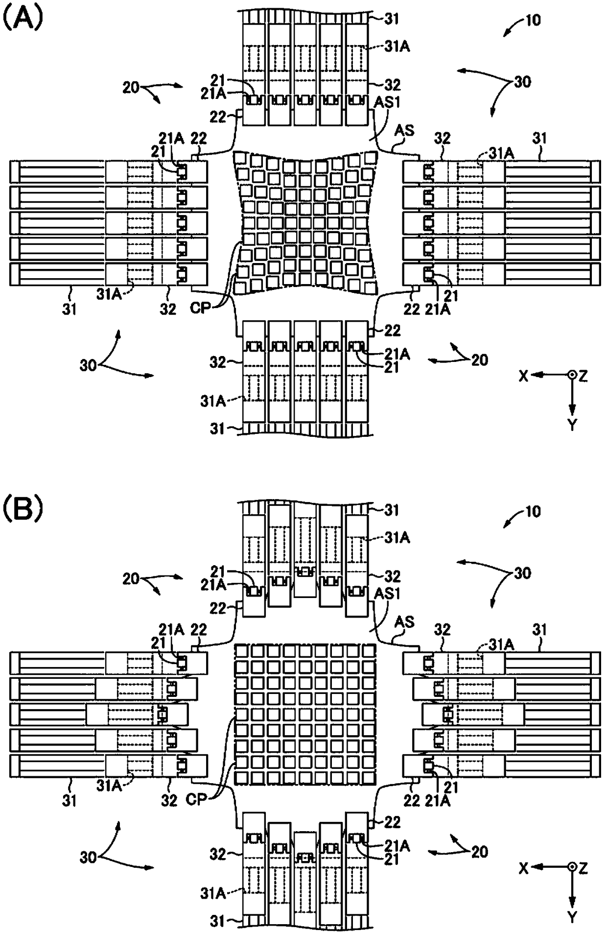
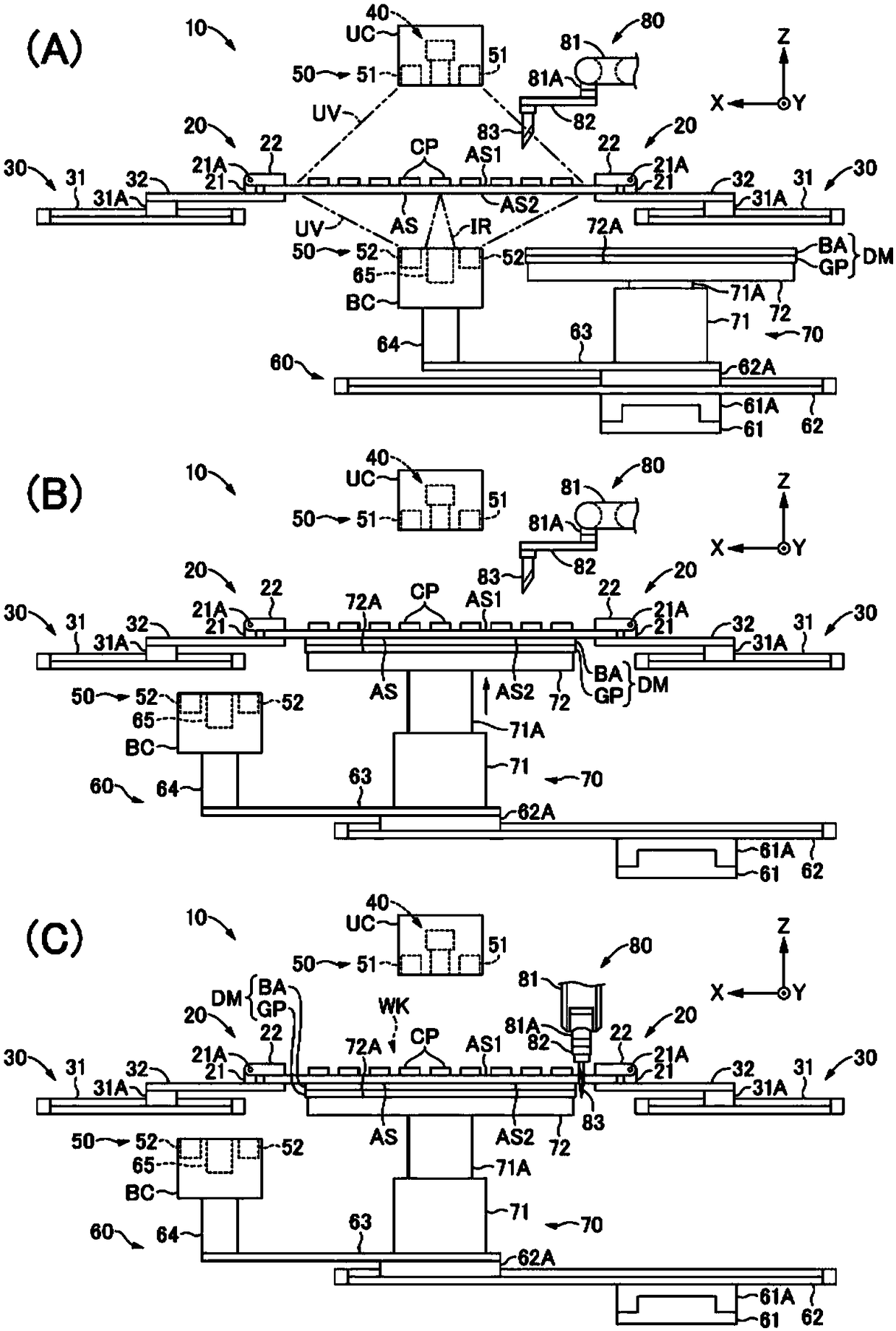
[0036] The separating device 10 of the present invention is provided with: a plurality of holding units 20, which hold the ends of the adhesive sheet AS on ...


PUM


Abstract

The invention provides a separating apparatus and a separating method, which are capable of making the mutual spacing of adherends as narrow as possible even if the tension applied to the adhesive sheet is released. The separating apparatus includes a plurality of holding units (20) that hold end portions of an adhesive sheet (AS), wherein at least one of one side (AS1) and the other side (AS2) ofthe adhesive sheet (AS) is adhered to adherends (CP); a separating unit (30) that enables the holding unit (20) holding the end of the adhesive sheet (AS) to relatively to move to enlarge the mutualspacing of the adherends (CP); the adherends (AS) which are formed to be solidified by being supplied with predetermined energy (UV). The separation apparatus is provided with a first energy supply unit (50) which supplies the predetermined energy (UV) to the adhesive sheet (AS) which achieves the enlarging of the separation of the adherends (CP) by the separation unit (30), so as to solidify theadhesive sheet (AS).

Description

technical field [0001] The invention relates to a separation device and a separation method. Background technique [0002] Conventionally, there is known a separating device that increases the mutual intervals between a plurality of adherends adhered to an adhesive sheet (for example, refer to Patent Document 1). [0003] prior art literature [0004] patent documents [0005] Patent Document 1: (Japanese) Unexamined Patent Application Publication No. 2016-127124 [0006] However, in the conventional separation device described in Patent Document 1, for example, when the sheet-shaped body (adhered body) whose mutual interval is enlarged on the adhesive sheet is conveyed together with the adhesive sheet, when the holding When the holding of the adhesive sheet by the unit is lost, the tension applied to the adhesive sheet is released, and the state closes to the state before deformation, so there is a disadvantage that the mutual interval between the adherends is narrowed. ...

Claims


Application Information

Patent Timeline
IPC IPC(8): H01L21/67H01L21/78
CPCH01L21/67092H01L21/78H01L21/67132H01L21/02
Inventor 杉下芳昭
Owner LINTEC CORP
Learn More