Charging circuit and charging method thereof

A charging circuit and circuit technology, applied in the field of communication, can solve problems such as explosions

Inactive Publication Date: 2018-10-23
ZTE CORP
View PDF5 Cites 2 Cited by
  • Summary
  • Abstract
  • Description
  • Claims
  • Application Information

AI Technical Summary

Problems solved by technology

[0002] With the popularization of fast charging technology, fast charging means high current, and high current will generate heat. Due to the design of mobile phones, the main board is generally on the upper part, and the Universal Serial Bus (USB) charging port

Method used


Image

  • Charging circuit and charging method thereof
  • Charging circuit and charging method thereof
  • Charging circuit and charging method thereof

Examples


Embodiment 1

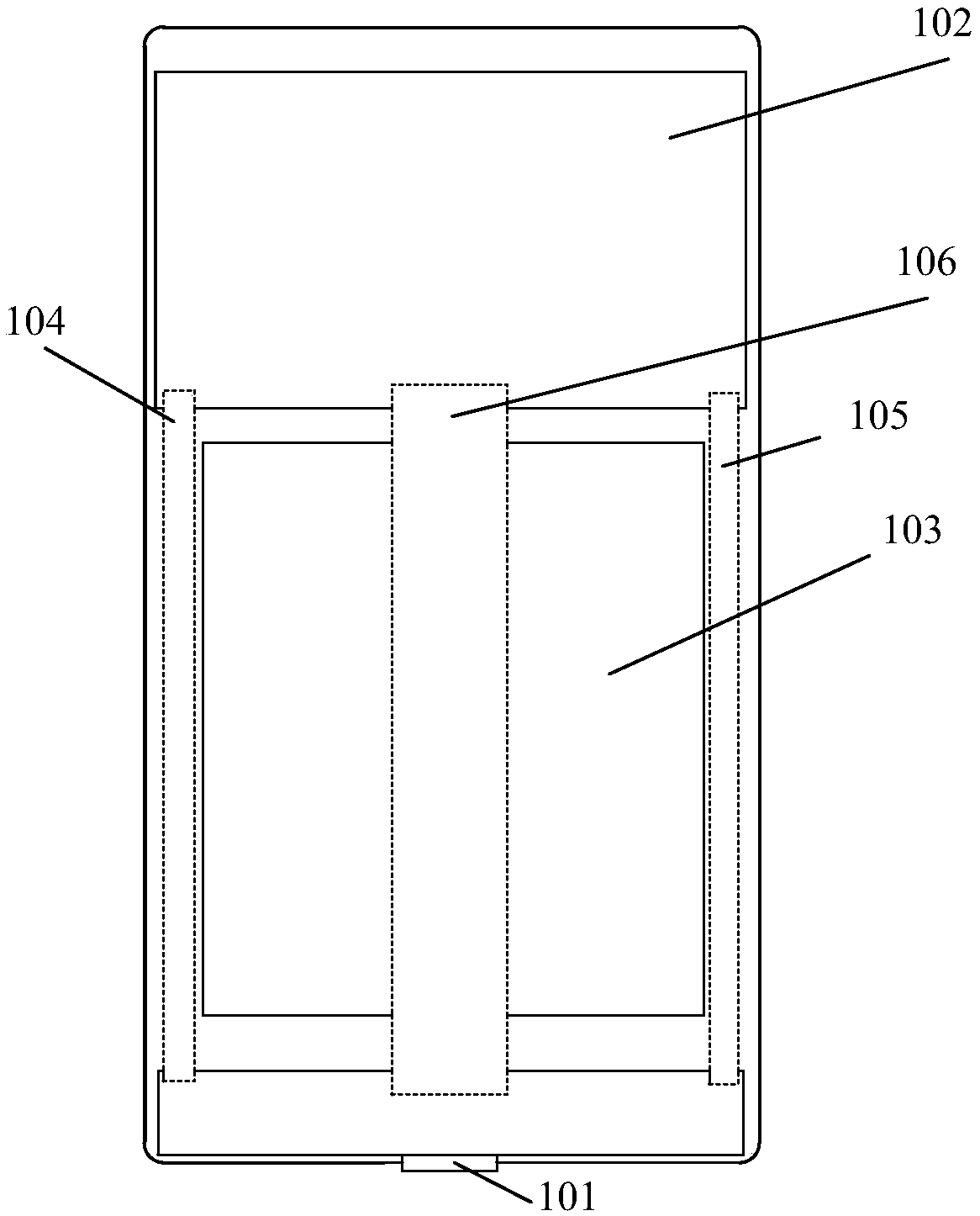
[0019] Embodiment 1 of the present invention provides a charging circuit, such as figure 1 As shown, the charging circuit includes: a USB interface 101, a motherboard 102, a battery 103, a first charging line 104 for transmitting current, a second charging line 105 for transmitting current, and a signal line 106 for transmitting data signals; wherein, the USB interface 101 is respectively Connect with the first end of the first charging line 104, the first end of the second charging line 105 and the first end of the third signal line 106; the second end of the first charging line 104 and the second end of the second charging line 105 The second end of the signal line 106 is connected to the main board 102 through the main board 102 .

[0020] Such as figure 1 As shown, the first charging line 104 , the second charging line 105 and the signal line 106 can be connected to the USB interface 101 through the daughter board 107 . In the embodiment of the present invention, the fir...

Embodiment 2

[0032]Based on the charging circuit described above, this embodiment provides a charging method for the charging circuit, the method comprising: when power is input to the USB interface, transferring the The current output by the USB interface is transmitted to the battery through the main board, and the transmission data signal output by the USB interface is sent to the main board through the signal line. The transmission of the charging current of the USB interface to the battery is completed through the first charging line and the second charging line, and the transmission of the data signal of the USB interface to the main board is completed through the signal line. When the data signal is transmitted to the main board, the processing of the main board is completed. The data signal is processed, and the operation corresponding to the data signal is performed.

[0033] Here, the USB interface is respectively connected to the first end of the first charging line, the first e...

Embodiment 3

[0038] In this embodiment, the charging circuit provided by the present invention is further described by taking the USB interface as USB3.0typeC, and the charging line and signal line as FPC as an example.

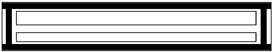
[0039] Here, will Figure 4 shown in the prior art charging circuit and figure 1 Shown charging circuit provided by the present invention is compared, specifically:

[0040] In the existing technology, such as Figure 4 As shown, the USB interface is connected to the motherboard through an FPC, and the motherboard is connected to the battery. Then, first of all, when charging the battery, the current of VBUS is concentrated on the FPC, and the heat is also concentrated on this FPC. When charging with a large current, the FPC heats up and heats up the battery as a whole. The performance of the battery will change, which will easily cause an explosion; secondly, there are three paths for charging backflow: the antenna cable, the magnesium-aluminum alloy frame, and the FP...


PUM


Abstract

The embodiments of the invention disclose a charging circuit. The charging circuit is characterized in that the circuit comprises a universal serial bus (USB) interface, a main board, a battery, a first charging line for transmitting current, a second charging line for transmitting current, and a signal line for transmitting data signals; the USB interface is connected with the first end of the first charging line, the first end of the second charging line, and the first end of the third signal line; the second end of the first charging line and the second end of the second charging line are connected with the battery through the main board; and the second end of the signal line is connected with the main board. The embodiments of the present invention also provide a charging method of theabove charging circuit.

Description

technical field [0001] The invention relates to the communication field, in particular to a charging circuit and a charging method thereof. Background technique [0002] With the popularization of fast charging technology, fast charging means high current, and high current will generate heat. Due to the design of mobile phones, the main board is generally on the upper part, and the Universal Serial Bus (USB) charging port is often on the bottom. The battery is between the USB port and the main board, so the charging circuit must pass through the battery, so the battery is susceptible to changes caused by the heating of the charging circuit, which may eventually cause an explosion. [0003] Based on this, there is an urgent need for a technical solution for the charging circuit, which can greatly reduce the dispersion density of the current, so that the heat can be dispersed and conducted faster, and prevent the battery of the mobile phone from heating when the mobile phone i...

Claims


Application Information

Patent Timeline
IPC IPC(8): H02J7/00
CPCH02J7/0029H02J7/0042H02J7/00H05K1/148H02J2310/22H02J7/00032H05K1/181
Inventor 龙玉其侯方西肖华
Owner ZTE CORP
Why Eureka
Try Eureka