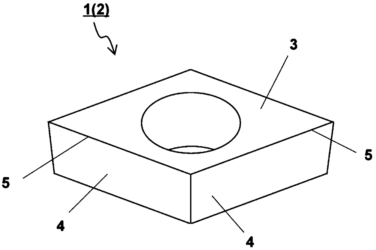
Supercharge Your Innovation With Domain-Expert AI Agents!

Cutting insert

A technology for cutting inserts and inserts, which is applied in the direction of cutting blades, turning equipment, accessories of toolholders, etc., and can solve the problem of insufficient smoothing of the processed surface

Active Publication Date: 2018-10-23
KYOCERA CORP
View PDF6 Cites 3 Cited by
  • Summary
  • Abstract
  • Description
  • Claims
  • Application Information

AI Technical Summary

Problems solved by technology

[0003] However, although the cutting insert described in the above-mentioned Patent Document 1 has the effect of improving the sharpness of the cutting edge, the effect of smoothing the machined surface of the workpiece is insufficient.

Method used


Image

  • Cutting insert
  • Cutting insert
  • Cutting insert

Examples


preparation example Construction

[0054] The mixed powder is prepared by adding a binder, a solvent, and the like to the above-mentioned weighed raw material powder, and mixing using a known mixing method such as a ball mill, a vibrating mill, a jet mill, and an ultrafine pulverizer. In this embodiment, a superfine pulverizer is used. The raw material powders are pulverized by powder mixing with an ultrafine pulverizer to reduce the particle size, but metal powders tend to be difficult to pulverize because of their high ductility. Then, the mixed powder is molded into a predetermined shape by a known molding method such as press molding, extrusion molding, and injection molding to produce a molded body.

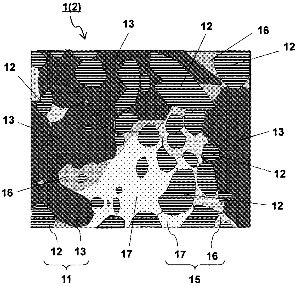
[0055] Next, according to the present embodiment, the molded body is fired in a vacuum or an inert gas atmosphere. According to the present embodiment, by firing under the following conditions, the base body 2 made of the cermet with the above-mentioned predetermined structure can be produced. As specific f...

Embodiment 1

[0067] By measurement based on the MICROTRAC method, TiCN powder with an average particle size of 0.6 μm, WC powder with an average particle size of 1.1 μm, TiN powder with an average particle size of 1.5 μm, TaC powder with an average particle size of 2 μm, and NbC powder with an average particle size of 1.5 μm, MoC powder with an average particle size of 2 μm, ZrC powder with an average particle size of 1.8 μm, VC powder with an average particle size of 1 μm, Ni powder with an average particle size of 2.4 μm and an average particle size of 1.9 μm Co powder, and W powder or WC 0.5 The powders were adjusted at the ratios shown in Table 1 to prepare mixed powders.

[0068] Isopropyl alcohol (IPA) and paraffin wax were added to the mixed powder, and a stainless steel ball mill and ultrahard balls were added, and mixed with an attritor to prepare a slurry. This slurry was granulated by spray drying to produce granulated powder, and the granulated powder was press-molded at 150 M...

Embodiment 2

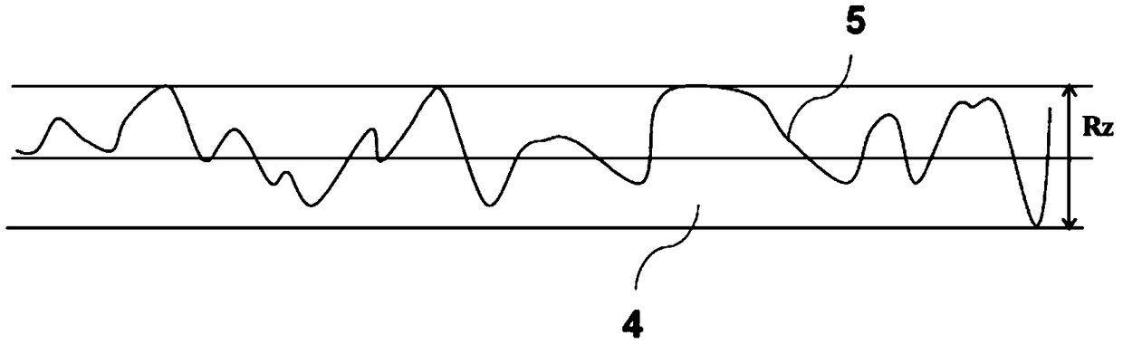
[0105] Using sample No. 1 of Example 1, the grinding method shown in Table 6 was changed and processed to produce cutting edges. For the obtained inserts, the maximum height, the arithmetic mean roughness, the residual stress of the first hard phase and the second hard phase, and the presence or absence and direction of grooves on the second surface were measured in the same manner as in Example 1. In addition, the cutting performance was evaluated under the same cutting conditions as in Example 1.

[0106] [Table 6]

[0107]

[0108] [Table 7]

[0109]

[0110] According to Tables 6 to 7, sample No. II- 1 to 3 are all products in which the surface roughness of the processed surface is smooth, there is no darkening of the processed surface, and the cutting length is poor.

[0111] In addition, in Sample Nos. II-1 and 2 in which the second surface has a plurality of grooves extending parallel to the cutting edge, the shape of the grooves is difficult to transfer to the...


PUM

PropertyMeasurementUnit
Radiusaaaaaaaaaa

Abstract

The cutting insert of an embodiment is provided with a base that has a first surface, second surfaces, and cutting edges. The base comprises hard phases and binding phases, and the hard phases comprise first hard phases and second hard phases. In X-ray diffraction analysis, the peak of the first hard phases is seen on the high angle side of the peak of the second hard phases. The second hard phases in the second surfaces have a compressive residual stress of at least 150 MPa. The maximum height (Rz) in the second surfaces is 0.2-1.5 [mu]m. The maximum height of the cutting edges is 2-30 timesthe maximum height in the second surfaces.

Description

technical field [0001] The present application relates to cutting inserts with cermets. Background technique [0002] Currently, cermets containing titanium as a main component are widely used as materials for cutting inserts used in cutting tools. Also, for example, JP 2002-126914 A (Patent Document 1) discloses a cutting insert in which the second surface is processed to a surface roughness of Ra of 0.08 μm or less to sharpen the cutting edge. [0003] However, although the cutting insert described in the above-mentioned Patent Document 1 has the effect of improving the sharpness of the cutting edge, the effect of smoothing the machined surface of the workpiece is insufficient. Contents of the invention [0004] A cutting insert according to one aspect includes a base body having a first surface, a second surface adjacent to the first surface, and a cutting edge positioned at an intersection edge between the first surface and the second surface. at least part of the de...

Claims


Application Information

Patent Timeline
IPC IPC(8): B23B27/14B22F3/10B22F7/00C22C1/05C22C29/04
CPCB22F3/10B22F7/00C22C1/05C22C29/04B23B27/14B22F2005/001B23C5/16B23B51/00C22C29/02C22C29/16B22F2998/10B22F3/02C23C16/36B22F3/162B22F5/00B22F2302/15B23B27/148B23B2200/0471
Inventor 野见山凉马前川纯也
Owner KYOCERA CORP
Features
  • R&D
  • Intellectual Property
  • Life Sciences
  • Materials
  • Tech Scout
  • Unparalleled Data Quality
  • Higher Quality Content
  • 60% Fewer Hallucinations
Learn More