Pipe cutting and beveling machine

一种管道切割、斜切机的技术,应用在剪管装置、剪切装置、便携式车床等方向,能够解决切割刀片振动、滑动、工作效率和生产率降低等问题

Active Publication Date: 2018-10-23
DCSENG CO LTD
View PDF6 Cites 9 Cited by
  • Summary
  • Abstract
  • Description
  • Claims
  • Application Information

AI Technical Summary

Problems solved by technology

Therefore, in order to replace the cutting blade or the chamfering blade in the middle of performing work or to perform other work, it is necessary to remove the cutter unit to replace the cutting blade or the chamfering blade, which leads to a problem of lowered work efficiency and productivity.
[0008] On the other hand, there is also the following problem: the entrance control unit 7 makes the cutter unit 8 enter the pipeline p side or retreat from the pipeline p side after the process is not fine-tuned, resulting in the inlet adjustment plate 6 due to the cutting load of the cutter unit 8. The phenomenon of sliding, the phenomenon that the fastening pressure of the inlet adjustment plate 6 is not adjusted to an appropriate level, and thus causes severe vibration of the cutting blade
However, when there is an error in the setting, it cannot be corrected in the setting state, and it needs to be set from scratch again
[0010] Since the inlet adjusting plate 6 is fixed by a simple action of tightening or loosening the fastening tool 14, when the cutting load of the cutter unit 8 is slightly increased, there occurs a phenomenon that the inlet adjusting plate 6 slides from the fastening tool 14, which makes the Precision Machining Becomes Impossible
[0011] In addition, the inlet control unit 7 for controlling the inlet adjustment plate 6 should have an appropriate gap with the rotary plate 4 in order to smoothly control the inlet adjustment plate 6. That is, when a large gap is generated, the cutter unit 8 during operation Application of severe vibration, which will significantly reduce the life of equipment and processing tools
When the gap is small, there will be a problem that the inlet adjustment plate 6 cannot be controlled
However, no device capable of adjusting this gap has been developed so far

Method used


Image

  • Pipe cutting and beveling machine
  • Pipe cutting and beveling machine
  • Pipe cutting and beveling machine

Examples


Embodiment Construction

[0036] Hereinafter, a pipe cutting and beveling machine according to an embodiment of the present disclosure will be described in detail with reference to the accompanying drawings.

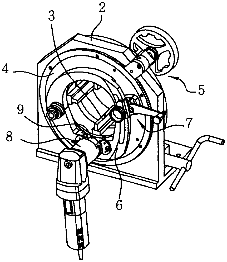
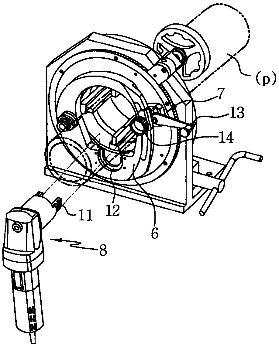
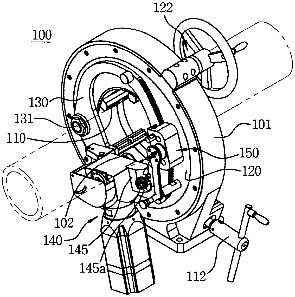
[0037] Such as image 3As shown, the pipe cutting and beveling machine 100 according to the present disclosure includes a main body 101 standing vertically as a basic skeleton. The main body 101 has a central part through which the pipe p to be cut or beveled passes, the machine means for cutting or beveling the pipe is attached to the front side of the main body 101 and the fixing means for clamping the pipe is attached to the main body 101 the rear side of the

[0038] First, in the apparatus, a rotating plate 120 concentrically rotating around the outer circumference of the fixed pipe p is attached to the main body 101 . The rotating plate 120 is connected to the main body 101 to be freely rotatable without being separated from the main body 101 , and the apparatus further includes a rotatio...


PUM


Abstract

Disclosed is a dedicated machine capable of cutting or beveling a pipe, such as a circular pipe or bar, in such a manner that a cutter unit rotates around the pipe while cutting any one surface of thepipe after gripping and fixing the pipe. A pipe cutting and beveling machine, according to the present invention, comprises: a main body unit in which a pipe passes through the center portion thereofso as to be fixed; and a cutter unit which is coupled to the main body unit so as to cut or bevel the pipe by means of a cutting blade while rotating around the fixed pipe, wherein the cutter unit may be provided with a rotating unit on one side thereof so as to pull the cutter unit aside and a locking unit on the other side thereof so as to restrain or release the cutter unit from being pulled aside. In addition, an entry control unit, which operates the cutter unit to move forward or backward, may comprise: a lever which is gear-engaged with an outer side surface of an entry control plate;and a clutch which is formed on a rotation shaft of the lever such that the restraint thereof is released when the lever is lifted or pressed in the axial direction.

Description

technical field [0001] The present invention relates to a machine capable of cutting or beveling pipes such as round pipe material, rod material etc. by fastening the pipe fixedly and then rotating the cutter unit around the pipe while the machine cuts one surface of the pipe. Background technique [0002] In the plumbing industry, the technique of cutting pipe or cutting and then beveling pipe is one of the processes that is as important as the welding technique. In the past, gas cutters, sawing machines, etc. were used for pipe cutting and mitering. However, in recent years, with the distribution of dedicated machines, their quality, operability and productivity have improved. [0003] Such as figure 1 As shown, the currently distributed special-purpose pipe cutting and beveling machines include: a main body 2 that allows the pipe to pass through and is connected with a plurality of jaws 3 to fix the pipe passing through the main body, connected to one side surface of th...

Claims


Application Information

Patent Timeline
Patent Type & Authority Applications(China)
IPC IPC(8): B26D3/16B26D7/26B26D7/02B26D7/20B23D21/04B23D33/02B23C3/12
CPCB23C3/12B23D21/04B23D33/02B26D3/16B26D7/02B26D7/26Y10T409/30644Y10T29/5199Y10T409/308512Y10T409/304144Y10T82/22B26D7/265B26D3/166B26D3/02B23B5/163B23B2215/72B23C1/12B23Q9/0035B23P23/02B26D7/20B23C3/122
Inventor 崔仁诚
Owner DCSENG CO LTD
Why Eureka
Try Eureka