Cooking device

A technology for cooking equipment and cooking chambers, which is applied to kitchen utensils, household utensils, roasters/barbecue grids, etc., and can solve problems such as obstructing air flow and energy waste, and achieve the degree of increased flow speed, fast flow speed, and cooked food uniform effect

Pending Publication Date: 2018-10-26
FOSHAN SHUNDE KUFU ELECTRIC APPLIANCES CO LTD
View PDF11 Cites 70 Cited by
  • Summary
  • Abstract
  • Description
  • Claims
  • Application Information

AI Technical Summary

Problems solved by technology

The air fryer with this structure has a simple frying basket structure, easy processing and cleaning of the bottom of the inner tank, and good support. In the above technical scheme, a guide tube is used to guide the gas to achieve uniform heating. However, the guide tube will hinder the flow of airflow, which will easily cause waste of energy

Method used


Image

  • Cooking device
  • Cooking device
  • Cooking device

Examples


Embodiment 1

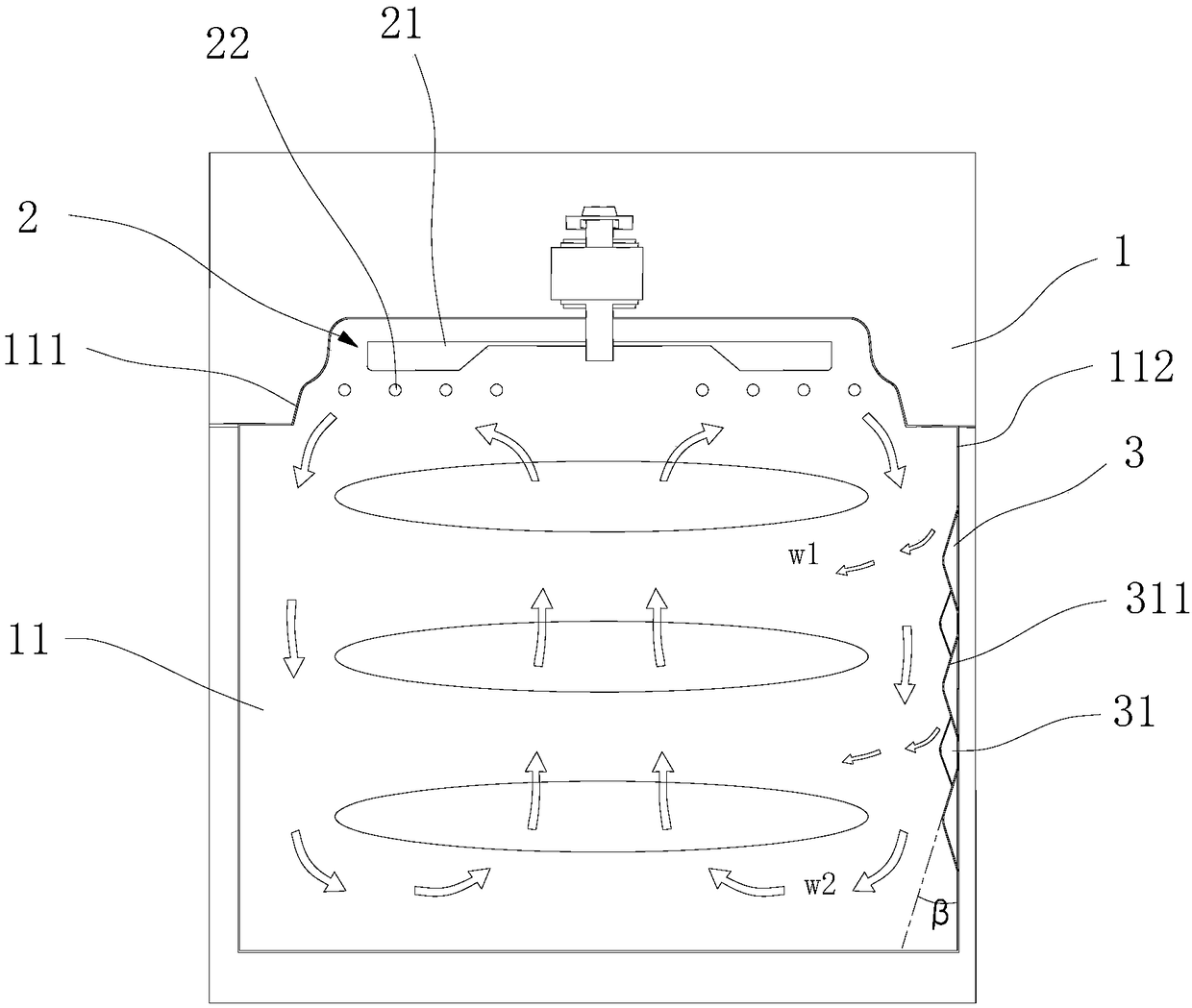
[0046] This embodiment provides a cooking device, such as figure 1 As shown, it includes a housing 1, a hot air flow generating device 2 and an air flow guiding device 3.

[0047] Wherein, a food cooking chamber 11 is provided inside the housing 1, and a hot air flow generating device 2 is provided inside the top of the food cooking chamber 11, and specifically includes a blowing device 21 and a heating device 22, wherein the blowing device 21 is used to generate flow The heating device 22 heats the airflow generated by the blowing device 21 to form a heating airflow. The food cooking chamber 11 has an air blowing hood 111, which is completely covered on the upper and outer sides of the air blowing device 21 and the heating device 22, wherein the heating airflow rotates and flows downward along the inside of the air blowing hood.

[0048] The food cooking chamber 11 has side walls 112, and one of the side walls 112 is provided with an airflow guide device 3 to force a portion (a sm...

Embodiment 2

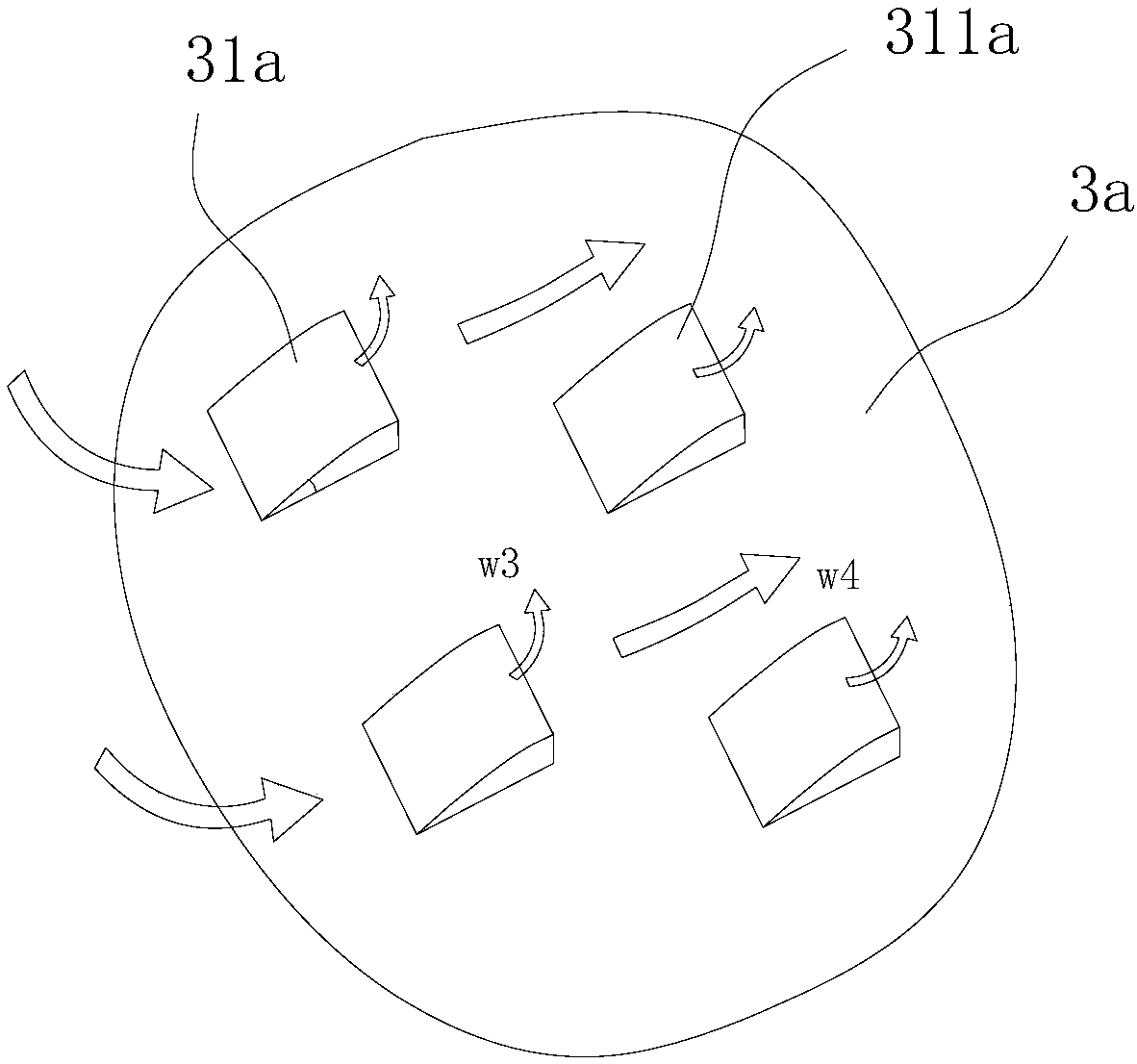
[0050] The difference between this embodiment and embodiment 1 lies in figure 2 As shown, the air guide device 3a in this embodiment has a plurality of guide portions 31a, the guide portion 31a has a guide surface 311a along the heating airflow into the guide portion 31a, the guide surface 311a is a curved surface, and a part (a small amount) of the heating airflow passes through After the guide surface, it rebounds along the guide surface 311a to form an auxiliary heating air flow w3 directly to the food surface, and part of the (main) heating air flow w4 continues to circulate along the original direction.

Embodiment 3

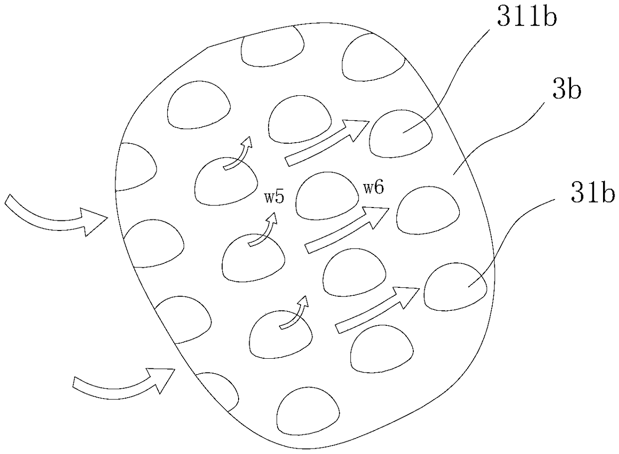
[0052] The difference between this embodiment and embodiment 1 lies in image 3 As shown, the airflow guide device 3b in this embodiment includes a plurality of spherical guide portions 31b. The guide surface 311b of the guide portion 31b is a spherical surface structure protruding along the inner side wall of the food cooking chamber, and partially (a small amount) is heated After the air flow passes through the guide surface 311b, it bounces back along the guide surface 311b to form an auxiliary heating air flow w5 directly to the food surface, and part of the (main) heating air flow w6 continues to circulate along the original direction.


PUM


Abstract

The invention provides a cooking device which comprises a shell and a hot-air flow generation device, wherein the shell is provided with a food cooking chamber, and the hot-air flow generation deviceis arranged at the top of the food cooking chamber. The hot-air flow generation device comprises a blowing device and a heating device positioned below the blowing device, the blowing device is used for generating flowed air flow, the heating part heats the air flow generated by the blowing device to form heated air flow, a blowing cover is arranged at the top of the food cooking chamber and completely covers the upper outer side of the blowing device and the heating device, the food cooking chamber is provided with side walls, at least parts of side walls are provided with air flow guide devices, and parts of heated air flow passes the air flow guide devices, then changes the flowed direction of the heated air flow and is scattered to the surface of food. According to the cooking device,the heated uniformity degree of the food in the making process can be improved, the quality and the taste of the food are improved, harmful heat is timely discharged in the making process of the food,and working stability of the device is improved.

Description

Technical field [0001] The invention belongs to the field of household appliances, and specifically relates to a cooking device with uniform heating. Background technique [0002] At present, most equipments that use high-temperature gas to heat food use high-speed hot air to directly blow over the surface of the food to heat the food. In this heating process, the high-temperature hot air is more concentrated, and the user needs to check whether the food is prepared or needed. The turning operation is performed to avoid the phenomenon of burnt and burnt; therefore, some cooking equipment using stirring devices have appeared, for example, a food cooking and / or heating electric device disclosed in Chinese Patent Document 201380055132.8, food cooking and / Or heating electric equipment includes: a housing with a cooking tube, the cooking tube is arranged to receive food to be cooked and / or to be heated; a ventilation heating circuit, which includes a ventilation hood with an outlet, ...

Claims


Application Information

Patent Timeline
Patent Type & Authority Applications(China)
IPC IPC(8): A47J37/06A47J37/04
CPCA47J37/047A47J37/0641A47J37/0664
Inventor 程晓梁福林肖丙三
Owner FOSHAN SHUNDE KUFU ELECTRIC APPLIANCES CO LTD
Why Eureka
Try Eureka