Energy-saving and environment-friendly flue gas denitrification device and method

An energy-saving and environmentally friendly flue gas technology, applied in the field of flue gas denitrification, can solve problems such as incomplete mixing of flue gas with reactants and catalysts, reduced efficiency and quality of flue gas denitrification, and incomplete flue gas denitrification, etc., to achieve increased Practicality, emission avoidance effect, long contact time effect

Pending Publication Date: 2018-10-26
张燕
View PDF7 Cites 4 Cited by
  • Summary
  • Abstract
  • Description
  • Claims
  • Application Information

AI Technical Summary

Problems solved by technology

[0002] Existing coal-fired boilers, industrial kilns and other industrial facilities will produce a large amount of flue gas containing nitrogen oxides when they are working. Nitrogen oxides are directly discharged into the air, which is easy to pollute the environment and affect people's health. Therefore, it is necessary to control the flue gas However, the existing flue gas contains large particles of dust, and the large particles of dust directly enter the flue gas denitrification device and easily block the device, reducing the efficiency and quality of flue gas denitrification, and the flue gas and reactants and catalysts Incomplete mixing and short contact time lead to incomplete flue gas denitrification. Therefore, we propose an energy-saving and environment-friendly flue gas denitrification device and method

Method used


Image

  • Energy-saving and environment-friendly flue gas denitrification device and method
  • Energy-saving and environment-friendly flue gas denitrification device and method
  • Energy-saving and environment-friendly flue gas denitrification device and method

Examples


Embodiment Construction

[0023] The following will clearly and completely describe the technical solutions in the embodiments of the present invention with reference to the accompanying drawings in the embodiments of the present invention. Obviously, the described embodiments are only some, not all, embodiments of the present invention. Based on the embodiments of the present invention, all other embodiments obtained by persons of ordinary skill in the art without making creative efforts belong to the protection scope of the present invention.

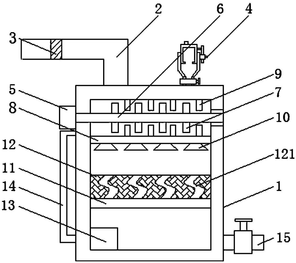
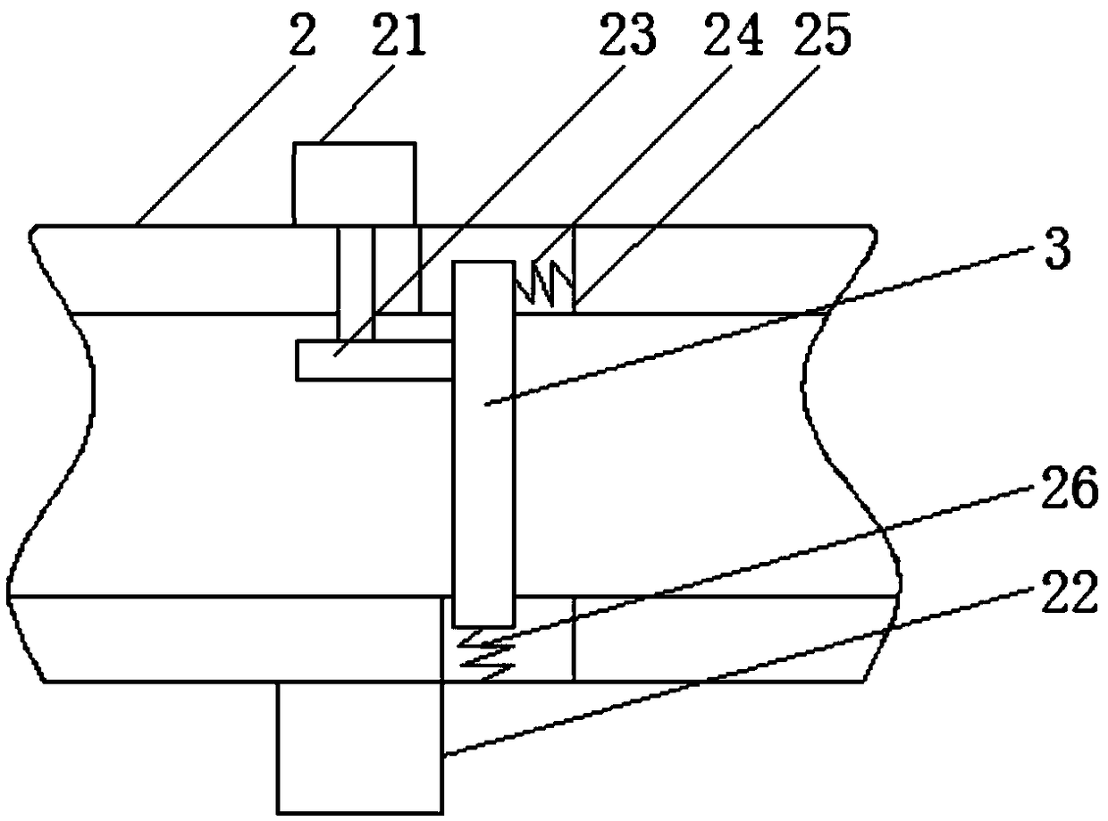
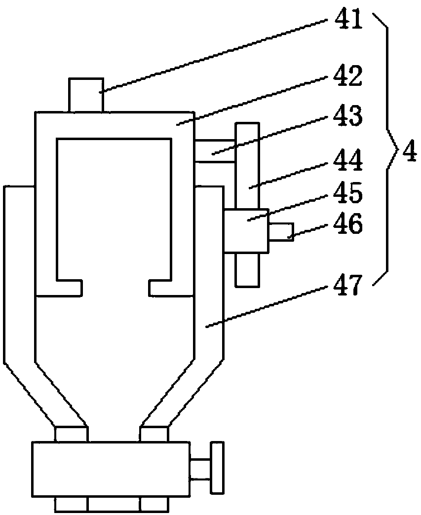
[0024] see Figure 1-4, the present invention provides a technical solution: an energy-saving and environment-friendly flue gas denitrification device, comprising a main body 1, an air intake pipe 2 is provided on the left side of the top of the main body 1, and a filter layer 3 is provided in the inner cavity of the air intake pipe 2 to remove the large particles of dust, to avoid dust from clogging the device, resulting in a decrease in flue gas denitrificat...


PUM


Abstract

The invention discloses an energy-saving and environment-friendly flue gas denitrification device and belongs to the technical field of flue gas denitrification. The energy-saving and environment-friendly flue gas denitrification device comprises a body, wherein a gas inlet pipe is arranged at the left side of the top of the body; a filtering layer is arranged in an inner cavity of the gas inlet pipe; spraying nozzles are uniformly arranged at the bottom of a liquid collection box; a catalysis layer is located just below the spraying nozzles; S-shaped circulation pipelines are uniformly formedin the inner cavity of the catalysis layer; a liquid suction pump is arranged at the left side of the bottom of an inner cavity of the body; a left-side outlet of the liquid suction pump extends to aleft-side outer wall of the body and is connected with a refluxing pipe; a discharging opening is formed in a right-side outer wall of the body; a valve is mounted on the discharging opening; flue gas is filtered through the filtering layer in the device and a condition that the device is blocked when large-particle dust enters the device is avoided; a reactant and flue gas are mixed completely through rotating a stirring blade, and the S-shaped circulation pipelines arranged in the inner cavity of the catalysis layer enable a mixture and the catalysis layer to be in contact for longer time,and furthermore, the flue gas denitrification efficiency is improved.

Description

technical field [0001] The invention relates to the technical field of flue gas denitration, in particular to an energy-saving and environment-friendly flue gas denitrification device and method. Background technique [0002] Existing coal-fired boilers, industrial kilns and other industrial facilities will produce a large amount of flue gas containing nitrogen oxides when they are working. Nitrogen oxides are directly discharged into the air, which is easy to pollute the environment and affect people's health. Therefore, it is necessary to control the flue gas However, the existing flue gas contains large particles of dust, and the large particles of dust directly enter the flue gas denitrification device and easily block the device, reducing the efficiency and quality of flue gas denitrification, and the flue gas and reactants and catalysts Incomplete mixing and short contact time lead to incomplete flue gas denitrification. Therefore, we propose an energy-saving and envir...

Claims


Application Information

Patent Timeline
Patent Type & Authority Applications(China)
IPC IPC(8): B01D53/90B01D53/56B01D46/10B01D46/00C02F1/58C02F103/18
CPCB01D46/10B01D53/8631B01D53/90C02F1/58C02F2103/18B01D2258/0283B01D46/76
Inventor 刘盈
Owner 张燕
Why Eureka
Try Eureka