Stamping die cleaning device

A technology for cleaning equipment and stamping dies, applied in cleaning methods and utensils, cleaning methods using liquids, cleaning methods using gas flow, etc. Easy and fast cleaning, practical and convenient operation, avoid the effect of product scrap

Pending Publication Date: 2018-10-26
JIANGSU DAZHONG ELECTRIC MOTOR
View PDF5 Cites 4 Cited by
  • Summary
  • Abstract
  • Description
  • Claims
  • Application Information

AI Technical Summary

Problems solved by technology

Generally, the mold is cleaned by hand with a wipe, which is time-consuming and labor-intensive, which increases the labor intensity of the workers. When cleaning, some corners are not cleaned thoroughly, which has a direct impact on the appearance quality of the processed product. If it is cleaned in an open space, Ash and slag are easy to fly everywhere, causing pollution to the environment. Using this cleaning method, the process is complicated, the cleaning efficiency is low, and a large amount of water is needed to clean the mold. Manual cleaning cannot reuse water resources, which is a waste of resources and increases Therefore, the invention patent with the application number of 201410366913.5 provides an automatic mold cleaning machine. Although the mold cleaning machine can clean the mold well, the structure of the mold cleaning machine is complicated and the cost is high. There are many steps, and the cleaning time is long. Moreover, since only one water tank is set up, it is necessary to drain the cleaning solution first, and then re-add clean tap water to continue cleaning the mold. Dilute the mold through tap water. The last cleaning, but after cleaning a relatively clean mold or a single mold, the cleaning liquid can still be used, and the cleaning liquid is directly discharged, which wastes water resources to a certain extent

Method used


Image

  • Stamping die cleaning device
  • Stamping die cleaning device
  • Stamping die cleaning device

Examples


Embodiment Construction

[0022] The following will clearly and completely describe the technical solutions in the embodiments of the present invention with reference to the accompanying drawings in the embodiments of the present invention. Obviously, the described embodiments are only some, not all, embodiments of the present invention. Based on the embodiments of the present invention, all other embodiments obtained by persons of ordinary skill in the art without creative efforts fall within the protection scope of the present invention.

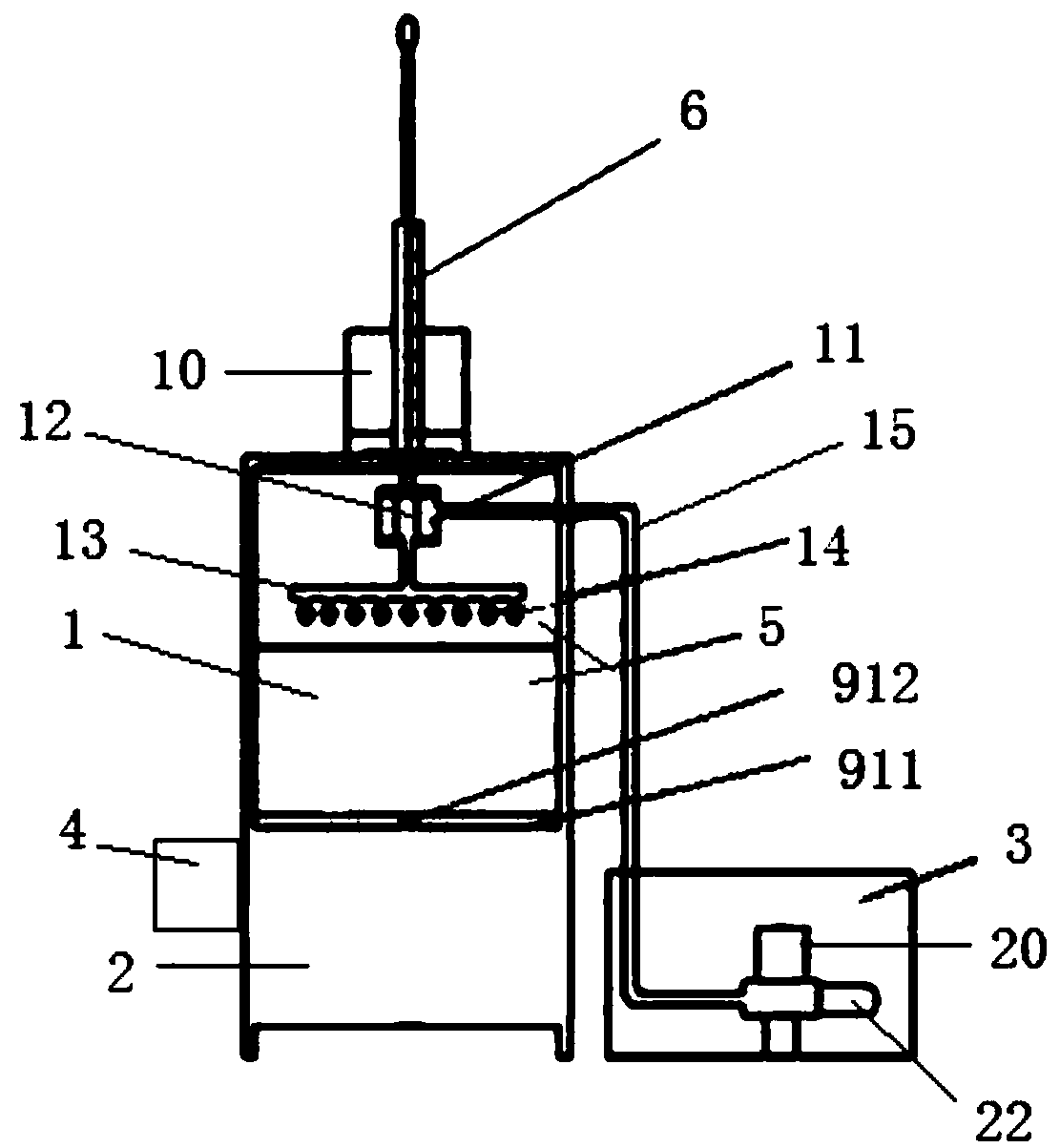
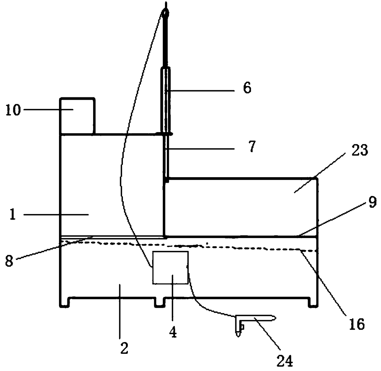
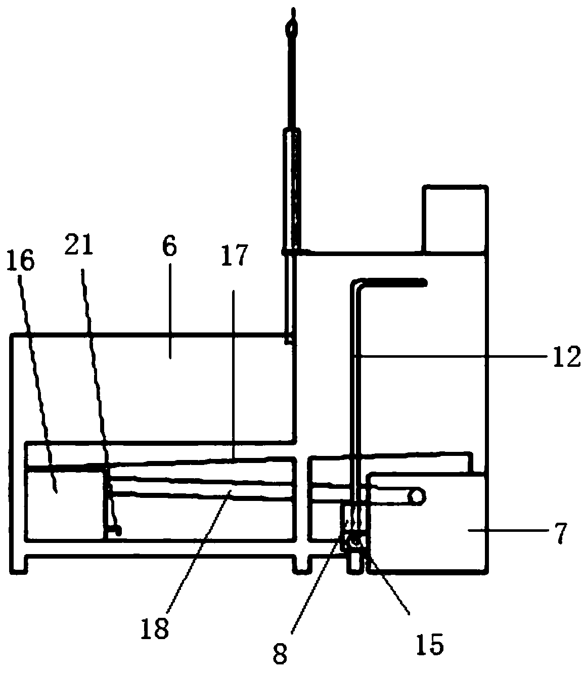
[0023] see Figure 1-5 , the present invention provides a technical solution: a stamping die cleaning equipment, including a cleaning chamber 1, a return chamber 2, a water supply chamber 3 and a control box 4, the return chamber 2 is located below the cleaning chamber 1, and the water supply chamber 3 Located on one side of the backwater chamber 2, the control box 4 is fixed on the side wall of the backwater chamber 2, and the front of the cleaning chamber 1 is pr...


PUM


Abstract

The invention relates to a stamping die cleaning device, and relates to the field of die cleaning. The stamping die cleaning device comprises a cleaning chamber 1, a water return chamber 2, a water supply chamber 3 and a control cabinet 4, wherein the water return chamber 2 is arranged under the cleaning chamber 1; the water supply chamber 3 is located on one side of the water return chamber 2; anelectromotor 10 and an air cylinder 6 are arranged on the outer side of the top part of the cleaning chamber 1; a bearing 7 is connected with a telescopic pneumatic door 5; a water storage cylinder 11 connected with the electromotor 10 is arranged on an inner wall of the top part of the cleaning chamber 1; a rotary rod 13 is arranged under the water storage cylinder 11; nozzles 14 are arranged onthe rotary rod 13; the water storage cylinder 11 is connected with the water supply chamber 3 through a water inlet pipe 15; an inclined clapboard 16 is arranged under a die placement table 9; a circular hole 17 is formed in the edge position of the rear end of the inclined clapboard 16; and a filter box 18 is arranged right under the circular hole 17 and is connected with the water supply chamber 3 through a water return pipe 19. The stamping die cleaning device provided by the invention can be used for effectively removing impurities adsorbed on the die surface and is faster compared with manual cleaning in the prior art.

Description

technical field [0001] The invention relates to the field of mold cleaning, in particular to a stamping mold cleaning equipment for mechanical processing. Background technique [0002] Due to the structural characteristics of the mold used in the motor punching process, after the grinding machine is sharpened, the grinding wheel chips, iron powder, oil, and dust generated after sharpening accumulate in the gap between the mold punch and the upper mold stripper plate. Difficult to remove, the friction resistance between the various parts of the mold is increased during the production and processing process, which leads to the phenomenon that the punching sheet does not fall off during the processing process, shortens the normal maintenance cycle of the mold, and reduces the service life of the mold. In order to stabilize the normal operation of the equipment and the quality of the product, it is necessary to clean and maintain the mold regularly. Generally, the mold is clean...

Claims


Application Information

Patent Timeline
Patent Type & Authority Applications(China)
IPC IPC(8): B08B3/02B08B3/08B08B3/14B08B5/02
CPCB08B3/02B08B3/08B08B3/14B08B5/02
Inventor 丁勇周剑叶海淀王荷芬刘霞刘蕾陈小东毛越峰
Owner JIANGSU DAZHONG ELECTRIC MOTOR
Why Eureka
Try Eureka