

A method for in-situ maintenance and purification of river and lake silt
A lake bottom sludge and silt technology, applied in chemical instruments and methods, sludge treatment, biological sludge treatment, etc., can solve the problems of low labor cost, high engineering investment and high energy price, achieve convenient equipment installation and avoid sludge diffusion , reducing the effect of sludge transportation
- Summary
- Abstract
- Description
- Claims
- Application Information
AI Technical Summary
Problems solved by technology
Method used
Image

Examples
Embodiment 1
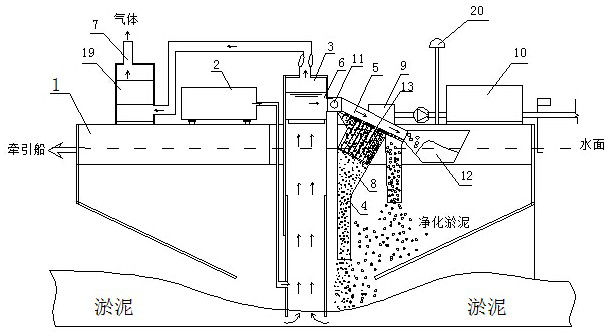
[0042]Such asfigure 1As shown, a river lake is used in a river or the purification treatment of river or lake sludge, and the river or lake is lifted to the hull or the hull in the river or lake through the method of lift. The sludge is aerated, and the pollution substances in sludge in the mud are subjected to microbial degradation of the river or lake in the river or the bottom of the silt purification chamber, and will be discharged from the bottom of the river or the bottom of the river or lake. .
[0043]The specific steps of the river lake sludge repair purification method are:
[0044]A: Silt boost: By setting the sludge in the hull 1 and extends to the river or lake bottom sludge, the sludge is lifted to the hull 1; the sludge is aerated, the pollutant in the oxidation of silt in the lifting process Make the volatile substance in the silt, with the airflow out, after the aeration, the mud enters the silt purification chamber 8;
[0045]B: Silt purification: Silled inoculation of micr...
Embodiment 2
[0050]In this example, improvements are performed on the basis of Example 1, and the improvement is also provided between the gas lifting device and the silt purification chamber 8, which is separated by a silt filtration device. Block solid contaminants.
[0051]The silt filter device is preferably a filter screen 13, which is disposed above the sludge purification chamber 8, and the filter screen 13 is in contact with the slope flow tube 5, and the other end is provided with a recovery chamber 12, the filtering The screen 13 is tilted downward to the recovery chamber 12, so that the sieved solid contaminants are inclined into the recovery chamber 12, and subsequent treatment is subsequently treated, avoiding it back to the river or lake, pollute the river or lake.
[0052]The specific steps of the river lake sludge repair purification method are:
[0053]A: Silled Lifting: By setting the sludge to the hull 1 by providing a lift lift in the hull or the river or lake bottom sludge, the lifti...
Embodiment 3
[0061]The present embodiment is improved on the basis of Example 2, and its improvement is further, and the gas-lifting device is provided with an air water separator between the silt filtering apparatus, and the mud passes through a gas water separator. Separate the gas, silt the muddy liquid; separated silt turbid fluid enters the silt purification chamber 8 through the silt filtering equipment.
[0062]Preferably, the gas water separator is attached to a gas purifying apparatus 19, and the gas separated by the gas water separator passes through the gas purification apparatus 19, and the gas purification is completed and then drained into the air.
[0063]The specific steps of the river lake sludge repair purification method are:
[0064]A: Silled Lifting: By setting the sludge to the hull 1 by providing a lift lift in the hull or the river or lake bottom sludge, the lifting fluid is promoted, and the silt is aerated during the promotion process, oxidized mud Pollution substances;
[0065]B1:...
PUM
 Abstract
Description
Claims
Application Information