Mixers for exhaust aftertreatment systems

A technology of exhaust post-treatment and mixer, which is applied in exhaust treatment, exhaust device, machine/engine, etc., can solve the problem of excessive exhaust back pressure in the mixer structure, uneven mixing of ammonia gas, and excessive mixer size. Large and other problems, to achieve the effect of good mixing effect, efficient mixing effect and small volume

Active Publication Date: 2019-11-15
WUXI WEIFU LIDA CATALYTIC CONVERTER
View PDF8 Cites 0 Cited by
  • Summary
  • Abstract
  • Description
  • Claims
  • Application Information

AI Technical Summary

Problems solved by technology

The existing structure has problems such as easy crystallization of urea, uneven mixing of ammonia gas, excessive exhaust back pressure of the mixer structure, and excessive size of the mixer.

Method used


Image

  • Mixers for exhaust aftertreatment systems
  • Mixers for exhaust aftertreatment systems
  • Mixers for exhaust aftertreatment systems

Examples


Embodiment Construction

[0028] The present invention will be further described below in conjunction with specific drawings and embodiments.

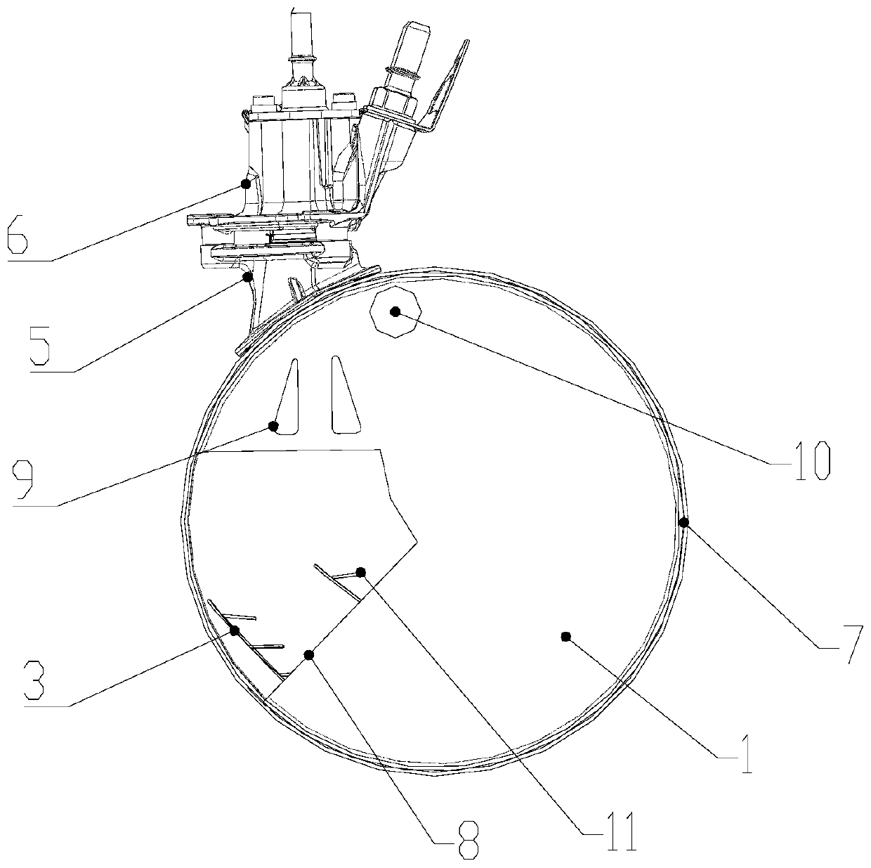
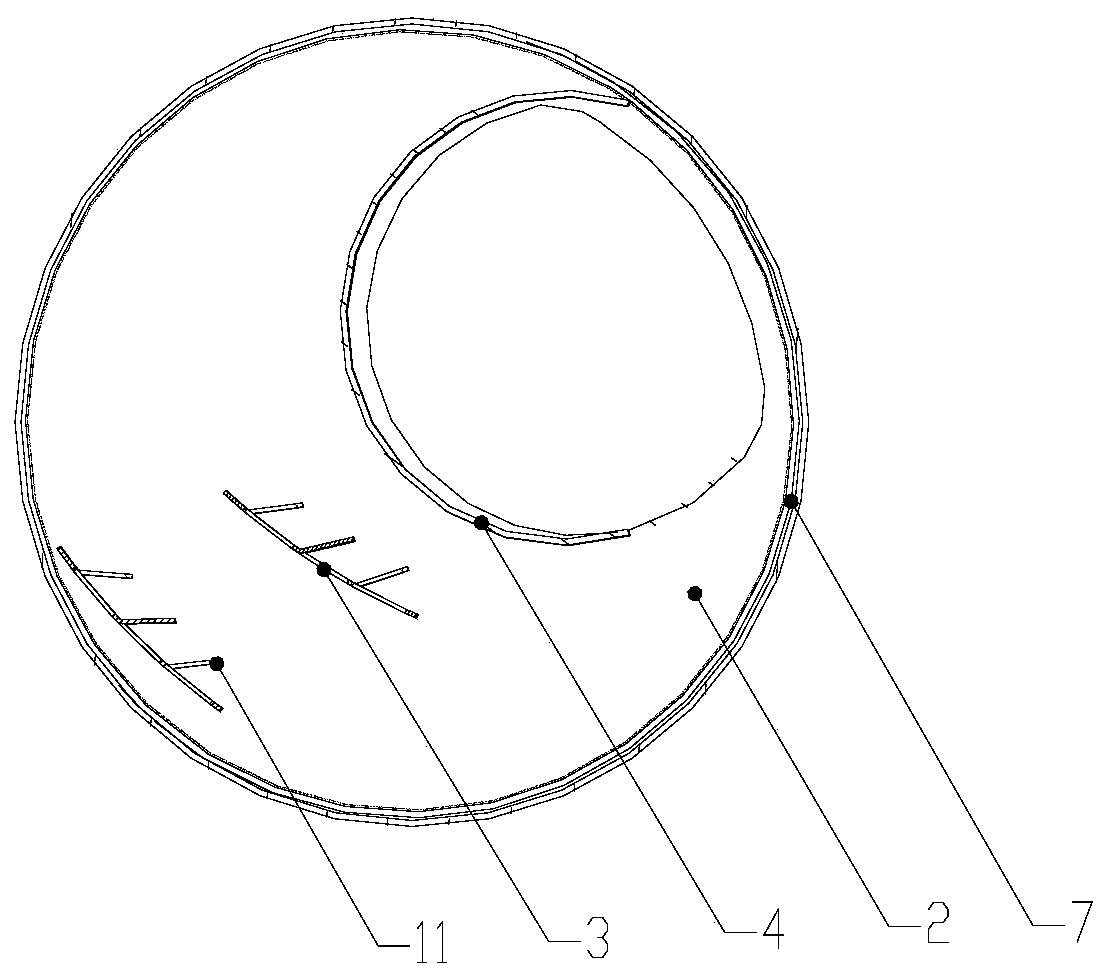
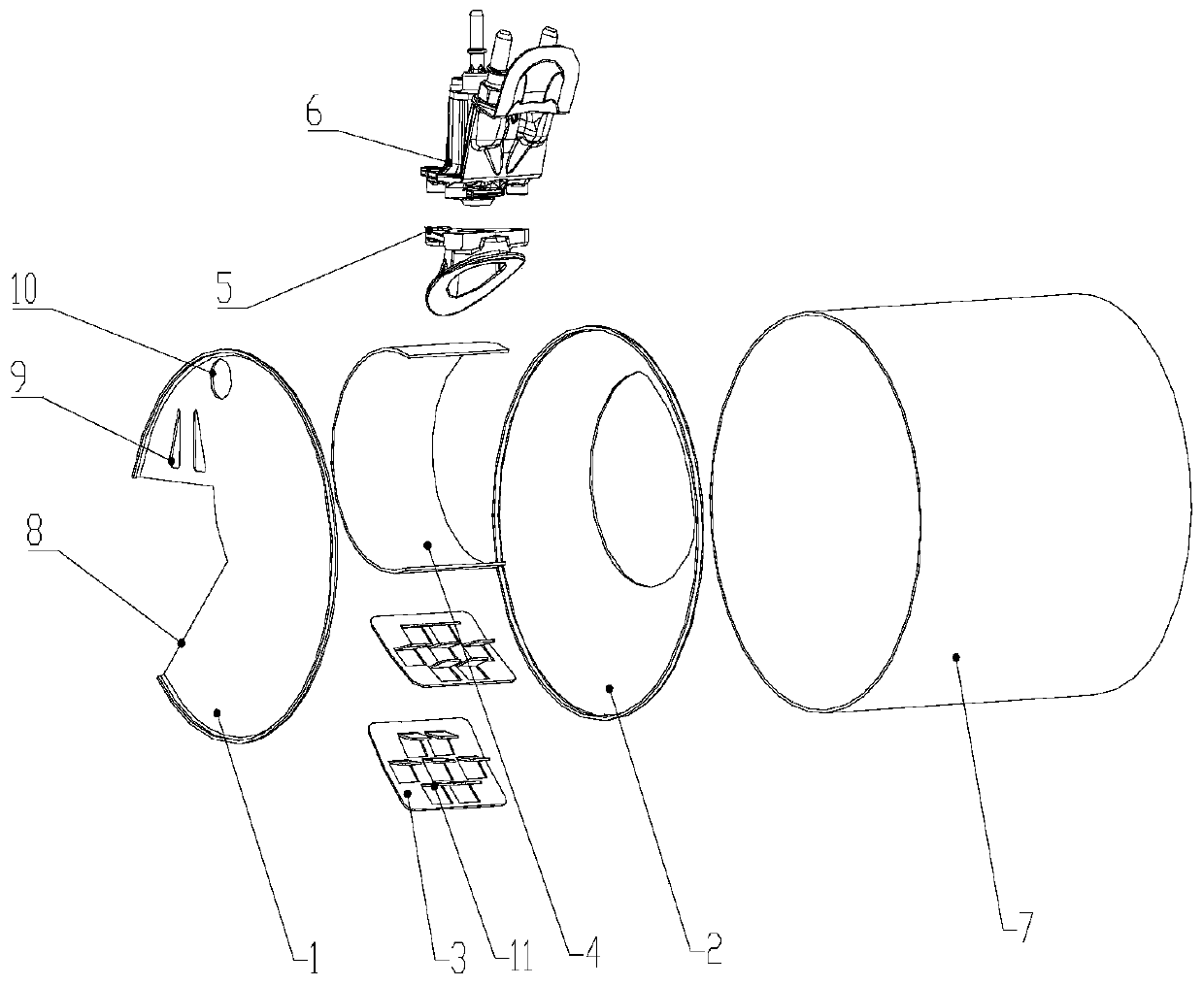
[0029] Such as Figure 1~Figure 3 As shown, the present invention provides a mixer for exhaust aftertreatment system, including a front baffle 1, a rear baffle 2, an arc plate 3, a cylindrical plate 4, a base 5, a nozzle 6 and a barrel 7 , where the front partition 1 and the rear partition 2 are installed inside the cylinder 7, the two ends of the arc plate 3 and the cylindrical plate 4 are connected to the front partition 1 and the rear partition 2, and the base 5 is installed on the cylinder 7 On, the nozzle 6 is installed on the base 5.

[0030] After the exhaust gas enters the exhaust system, it goes from DOC to DPF and then reaches the front end of the mixer. At this time, the gas is evenly distributed in the cross-sectional direction of the cylinder 7. Under the drainage effect of the front bulkhead 1, the exhaust gas passes through the through holes of...


PUM


Abstract

The invention relates to a mixer for an exhaust aftertreatment system. The mixer comprises a front clapboard, a rear clapboard, an arc-shaped plate, a cylindrical plate, a base, a nozzle and a barrel,wherein the front clapboard and the rear clapboard are arranged in the barrel; the distance between the two clapboards is arranged to be from 75 to 100mm; two ends of the arc-shaped plate are connected onto the front clapboard and the rear clapboard; two ends of the cylindrical plate are connected onto the front clapboard and the rear clapboard; the base is arranged on the barrel; and the nozzleis arranged on the base. According to the device, urea can be ensured to be uniformly distributed on the end surface of a selective catalytic reduction (SCR) carrier, an exhausted gas and an ammonia gas are uniformly mixed, and SCR can work efficiently and stably. Meanwhile, the mixer is small in structure size, and conforms to the strict boundary requirement of a finished automobile on a packaging structure.

Description

technical field [0001] The invention belongs to the technical field of diesel engine exhaust aftertreatment, and in particular relates to a mixer used in an exhaust aftertreatment system. Background technique [0002] With the development of the national emission standards for diesel vehicle exhaust pollutants to the Euro VI stage, more stringent emission standards have stricter definitions for exhaust pollutants. Selective Catalytic Reduction (SCR) technology has become the first choice of major domestic OEMs. The principle of SCR technology is to use the NH produced by the decomposition of urea 3 , under the action of catalyst, with NO X The reaction produces N 2 , thereby reducing NO in the exhaust X , to treat the exhaust gas to meet Euro VI emission standards. [0003] The mixer is usually arranged before the selective catalytic reduction converter, at the back end of the oxidation catalyst (Diesel OxidentCatalyst, DOC) and the diesel particulate filter (Diesel Par...

Claims


Application Information

Patent Timeline
Patent Type & Authority Patents(China)
IPC IPC(8): F01N3/28
CPCF01N3/2892F01N2570/14F01N2610/02Y02A50/20
Inventor 张旭陈增响郭鑫何龙付细平
Owner WUXI WEIFU LIDA CATALYTIC CONVERTER
Why Eureka
Try Eureka