Steam turbine full cylinder state flow clearance detection method
A detection method and steam turbine technology, applied in the direction of measuring devices, instruments, and optical devices, can solve the problems of low precision in the flow gap, achieve the effects of improving measurement accuracy, saving manpower and material resources, and shortening delivery time
- Summary
- Abstract
- Description
- Claims
- Application Information
AI Technical Summary
Problems solved by technology
Method used
Image
Examples
specific Embodiment approach 1
[0023] Embodiment 1: A method for detecting a flow gap in a steam turbine full cylinder state includes the following steps:
[0024] Step 1. In the split and merged states of the diaphragms at all levels, use the laser tracker API-T3 to measure the inner circles of the diaphragms at the shaft sections at all levels and the inner circles of the diaphragms at the rotor blades at all levels;
[0025] Step 2. In the state of dismantling the cylinder, use the laser tracker API-T3 to use the target ball to measure the circular arcs at all levels required for the flow gap of the upper and lower cylinders;
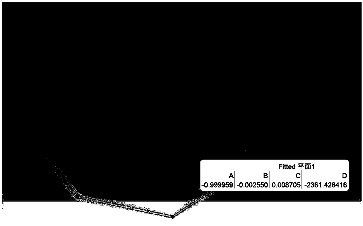
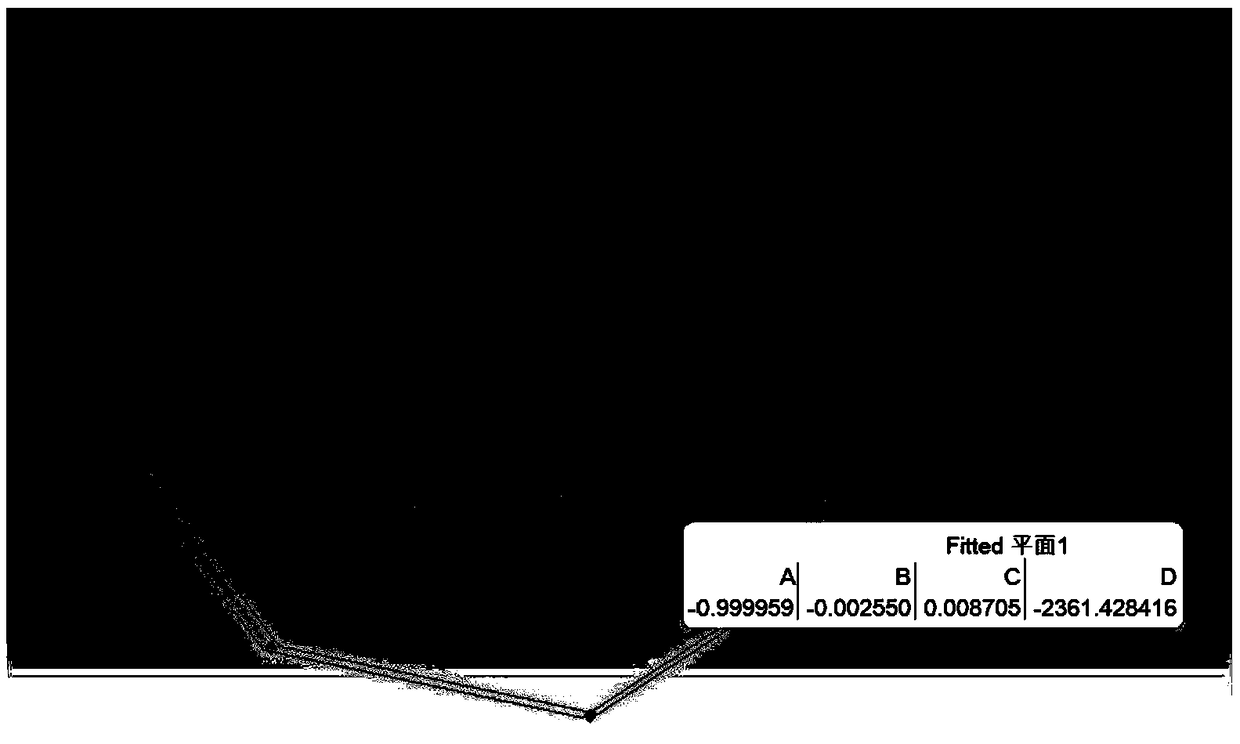
[0026] Step 3, utilize SpatialAnalyzer software to process the data measured in step 1 and step 2, extract the center of circle and diameter;
[0027] Open the measured data in SA, such as fitting a circle or a plane, select the fitting geometry (circle or plane), and select the measurement point to be fitted, after the fitting, check the fitting error, if the fitting If the erro...
specific Embodiment approach 2
[0030] Specific embodiment 2: The difference between this embodiment and specific embodiment 1 is that in the step 1, when the partitions at all levels are split and merged, the laser tracker API-T3 is used to measure the shaft segment partitions at all levels The specific process of the inner circle and the inner circle of the diaphragm at the rotor blades at all levels is as follows:
[0031] Step 11: In order to use the laser tracker to collect the data of the partition, it is necessary to adjust the partition to a horizontal state on the detection platform, and the levelness error is less than 0.05mm; the API-T3 laser tracker is preheated for 20 to 40 minutes, and then Calibration; when measuring half a partition, 6 to 10 positions on the arc are roughly evenly collected on the half partition, and 20 to 100 points are collected for each position;
[0032] Step 1 and 2: When measuring the spliced partitions, it is necessary to place the partitions on the detection platfor...
specific Embodiment approach 3
[0035] Specific embodiment 3: The difference between this embodiment and specific embodiment 1 or 2 is that in the step 2, in the state of dismantling the cylinder, the laser tracker API-T3 is used to measure the flow gap requirements of the upper and lower cylinders by using the target ball. The details of arcs at all levels are:
[0036] When measuring the arcs at all levels required by the flow gap on the cylinder, there are some seal teeth on the cylinder, and the seal teeth are sharp and thin arcs. The small steam turbine adopts the steam seal gear seal to seal the internal spaces of the cylinder at all levels, so that the steam generated from the intake end of the steam turbine can flow from the diaphragm and rotor blades as much as possible, and the number and types of seal teeth are more , and the seal tooth and the diaphragm are in a spring connection state. During the measurement process with the target ball, placing the target ball directly on the seal tooth will co...
PUM
 Abstract
Description
Claims
Application Information
 - R&D
- Intellectual Property
- Life Sciences
- Materials
- Tech Scout
- Unparalleled Data Quality
- Higher Quality Content
- 60% Fewer Hallucinations
Browse by: Latest US Patents, China's latest patents, Technical Efficacy Thesaurus, Application Domain, Technology Topic, Popular Technical Reports.
© 2025 PatSnap. All rights reserved.Legal|Privacy policy|Modern Slavery Act Transparency Statement|Sitemap|About US| Contact US: help@patsnap.com


