
An Optimal Active Disturbance Rejection Control Method for Propelling Force of Roof Bolter Rig

A technology of active disturbance rejection control and bolt drilling rig, applied in drilling equipment and methods, installation of bolts, rotary drilling, etc., can solve the problems of low reliability, inability to adapt to rock formation changes, lack of Efficiency and driving speed, the effect of solving the large dependence on work experience

Active Publication Date: 2022-03-15
CHINA UNIV OF MINING & TECH
View PDF10 Cites 0 Cited by
  • Summary
  • Abstract
  • Description
  • Claims
  • Application Information

AI Technical Summary

Problems solved by technology

[0008] Patent (Lu Jianbo, Pan Kaifang, Hu Renchun, etc. The Realization of Drilling Rig Nudge Opening, Self-adaptive Capability and Automatic Anti-Stuck Function [P], CN 101358522A, 2009.02.4) Solve the manual The drilling rig control method cannot adapt to the shortage of rock formation changes
[0009] At present, the research on the propulsion force of drilling rigs is mainly concentrated in two aspects: on the one hand, the adaptive control of the propulsion force of drilling rigs is realized by using proportional pressure regulating pumps, load sensing devices, high-speed switching valves and other components, and the reliability of this method is low; the other On the one hand, according to the collected slewing pressure information, the proportional valve and the variable pump are used to realize the logic control of the propulsion force
Adaptive control of propulsion cannot be achieved due to the lack of optimal propulsion estimation under different surrounding rocks

Method used


Image

  • An Optimal Active Disturbance Rejection Control Method for Propelling Force of Roof Bolter Rig
  • An Optimal Active Disturbance Rejection Control Method for Propelling Force of Roof Bolter Rig
  • An Optimal Active Disturbance Rejection Control Method for Propelling Force of Roof Bolter Rig

Examples


Embodiment Construction

[0065] The present invention will be further described below in conjunction with the accompanying drawings. The following examples are only used to illustrate the technical solution of the present invention more clearly, but not to limit the protection scope of the present invention.

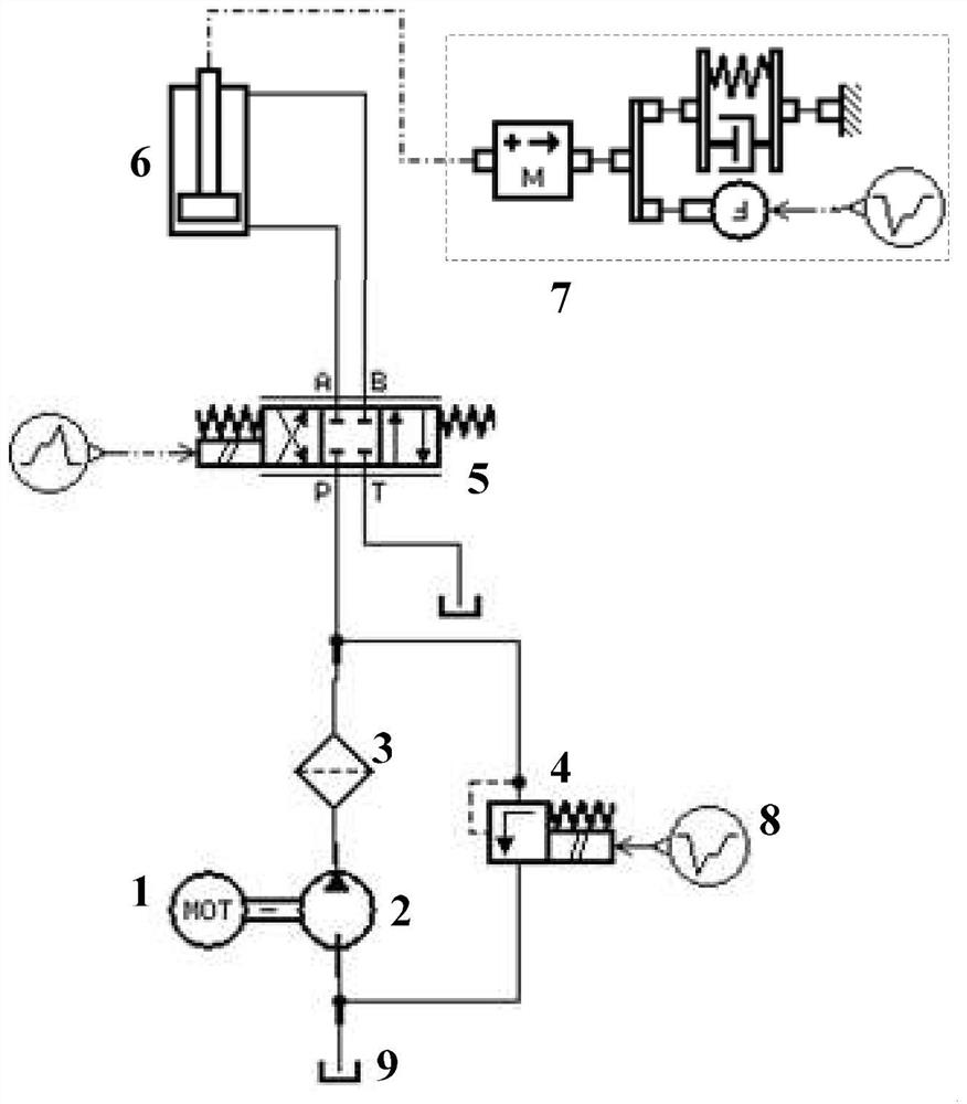
[0066] This method firstly sets the optimal propulsion force according to the properties of the surrounding rock; secondly, considering the nonlinearity, time-varying parameters and multi-interference characteristics of the hydraulic system of the rock bolter, the active disturbance rejection controller is used to realize the propulsion control of the drilling rig; finally, Considering the requirements of fast response and dynamic stability of the system, the particle swarm optimization algorithm is used to adaptively adjust the parameters of the ADRC controller to ensure the best response performance of the drilling rig propulsion system.

[0067] In this embodiment, the values ​​of the core pa...


PUM


Abstract

The invention discloses an optimal self-disturbance rejection control method for the propulsion force of a rock bolt rig, which is characterized in that it comprises the following steps: step 1) establishing a mathematical model of the propulsion system of a rock bolt rig; step 2) using the drilling rig information to set The optimal propulsion force of the drilling rig for the current drilling; Step 3) Combined with the particle swarm optimization algorithm, design the optimal active disturbance rejection controller; Step 4) Based on the joint simulation platform of Matlab and AMESim, verify the control of the proposed rock bolter propulsion system The validity and rationality of the method. Beneficial effects achieved by the present invention: the present invention is applicable to the optimal control of the propulsion force of the rock bolter, and solves the problem that the control of the traditional drilling rig is highly dependent on the working experience of the operator; the drilling rig can self-adaptively adjust the propulsion according to the properties of the drilling surrounding rock In this way, failures such as broken rods and other rods of the drilling rig can be reduced, work efficiency and excavation speed can be improved, and the foundation for the automation and intelligence of the drilling rig can be laid.

Description

technical field [0001] The invention relates to an optimal self-disturbance rejection control method for the propulsion force of a rock bolt rig, and belongs to the technical field of engineering machinery automatic control. Background technique [0002] The rock bolt rig is one of the key equipment in the construction of geotechnical anchoring engineering, and its equipment performance directly determines the progress and quality of the entire project. This patent mainly studies the axial propulsion control of a rock bolter. During the drilling operation, the propulsion mechanism exerts a certain axial force on the drill bit, so that the drill bit is in close contact with the rock, and effectively assists the slewing mechanism to break the rock. Studies have shown that proper propulsion will make the drilling rig work in the optimal rock drilling area, and the maximum drilling efficiency and speed can be obtained. If the propulsion force is too small, the drill bit will n...

Claims


Application Information

Patent Timeline
Patent Type & Authority Patents(China)
IPC IPC(8): G06F30/27E21D20/00E21B3/02F15B11/00F15B13/02
CPCE21B3/02E21D20/003F15B11/00F15B13/02G06F30/20
Inventor 郭一楠程伟陆希望巩敦卫程健杨帆
Owner CHINA UNIV OF MINING & TECH
Learn More