Low sampling rate-based time reversion wireless energy transmission system and method

A time inversion, wireless energy transmission technology, applied in electrical components, circuit devices, etc., can solve the problems of high cost, low transmission efficiency, short transmission distance, etc., to reduce the difficulty and cost of physical implementation, long transmission distance, and efficiency. high effect

Active Publication Date: 2018-10-26
SOUTH CHINA UNIV OF TECH
View PDF3 Cites 2 Cited by
  • Summary
  • Abstract
  • Description
  • Claims
  • Application Information

AI Technical Summary

Problems solved by technology

Nowadays, wireless energy transmission in the form of electromagnetic wave radiation has the problems of low transmission efficiency and short transmission distance
[0004] In recent years, in order to solve the problems of low transmission efficiency and short transmission distance, some scholars have proposed a new wireless energy transmission technology based on time-reversal electromagnetic wave transmission. Using this technology, electromagnetic waves can realize time and space in complex multipath environments. Synchronous focus, with this feature to improve the transmission efficiency and transmission distance of wireless energy transmission, and realize simultaneous charging of multiple devices without complex positioning system
Because in the time-reversal wireless energy transmission system, the use of broadband high-frequency signals can obtain better focusing effect and energy transmission efficiency, therefore, at present, in the time-reversal wireless energy transmission system, the time Before and after inversion processing, high-speed AD / DA conversion devices are usually used, which makes the realization of wireless energy transmission system difficult and costly

Method used


Image

  • Low sampling rate-based time reversion wireless energy transmission system and method
  • Low sampling rate-based time reversion wireless energy transmission system and method
  • Low sampling rate-based time reversion wireless energy transmission system and method

Examples


Embodiment Construction

[0044] The following will clearly and completely describe the technical solutions in the embodiments of the present invention with reference to the accompanying drawings in the embodiments of the present invention. Obviously, the described embodiments are only some, not all, embodiments of the present invention. Based on the embodiments of the present invention, all other embodiments obtained by persons of ordinary skill in the art without making creative efforts belong to the protection scope of the present invention.

[0045] In order to make the above objects, features and advantages of the present invention more comprehensible, the present invention will be further described in detail below in conjunction with the accompanying drawings and specific embodiments.

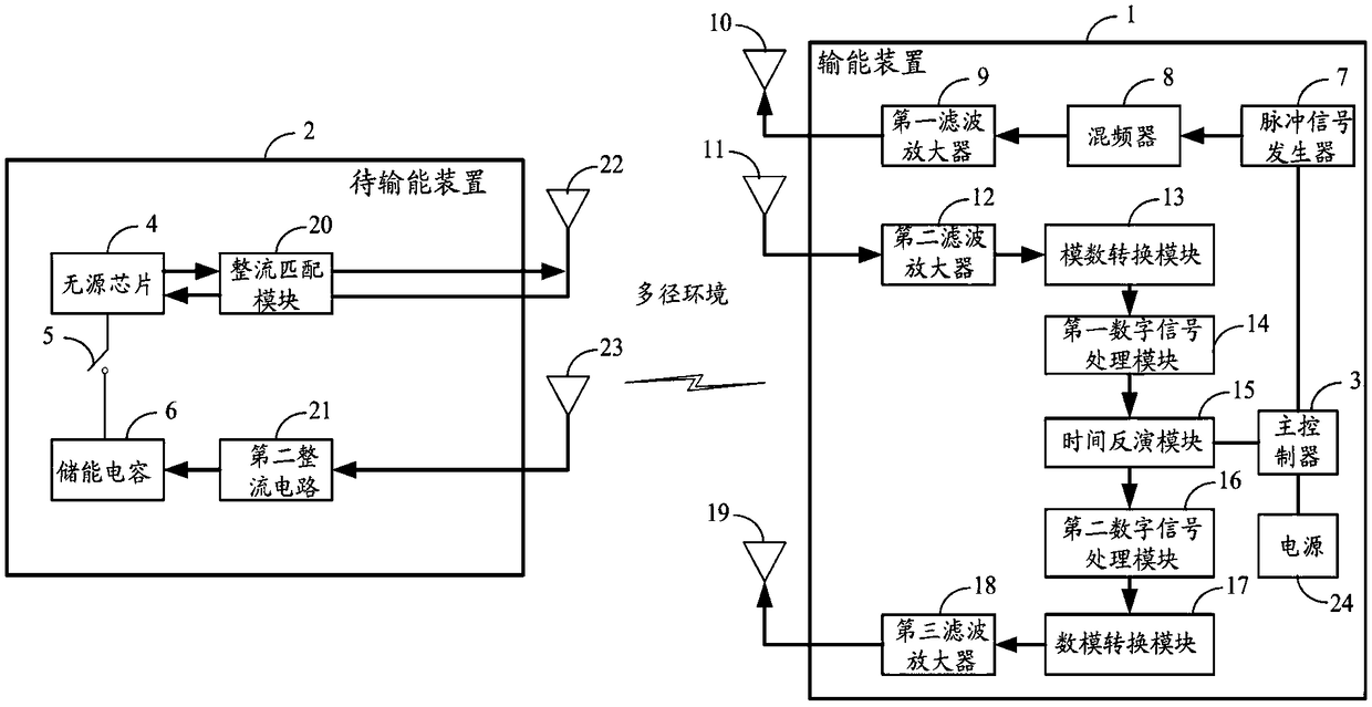
[0046] figure 1 It is a schematic structural diagram of a time-reversal wireless energy transmission system based on a low sampling rate according to an embodiment of the present invention.

[0047] see figure 1...


PUM


Abstract

The invention discloses a low sampling rate-based time reversion wireless energy transmission system and method. An energy transmission device in the system comprises a master controller, a detectionsignal generation device and a reverse signal generation device, the device to be energy-transmitted comprises a passive chip, a switch circuit, an energy storage capacitor and a rectification matching module, the master controller is connected with the detection signal generation device and the reverse signal generation device, the detection signal generation device and the reverse signal generation device both are in wireless connection with the device to be energy-transmitted, the passive chip is connected with the rectification matching module and is connected with an energy storage capacitor via the switch circuit, an analog-to-digital conversion module in the reverse signal generation device comprises a plurality of low-rate analog-to-digital converter, the digital-to-analogue conversion module, a first digital signal processing module, a time reversion module, a second digital signal processing module and the analog-to-digital conversion module are sequentially connected, and the analog-to-digital conversion module comprises the plurality of low-rate digital-to-analogue convertors. The system is easy to implement, is low in cost, far in transmission distance and high in efficiency.

Description

technical field [0001] The invention relates to the technical field of wireless energy transmission, in particular to a time-reversal wireless energy transmission system and method based on a low sampling rate. Background technique [0002] With the popularization of mobile devices and the development of the Internet of Things, the traditional wired energy transmission method has been difficult to meet people's needs, and wireless energy transmission has become one of the important modules in many mobile applications, especially for some special cases where the battery cannot be replaced , such as embedded micro-devices implanted in the human body, wireless energy transmission is the only convenient and effective way of energy supply. [0003] The realization of wireless energy transmission can be divided into three types, one is coil induction wireless power transmission technology based on vortex electromagnetic field theory, which relies on the electromagnetic induction b...

Claims


Application Information

Patent Timeline
Patent Type & Authority Applications(China)
IPC IPC(8): H02J50/20
CPCH02J50/20
Inventor 胡斌杰廖鹏林志武
Owner SOUTH CHINA UNIV OF TECH
Why Eureka
Try Eureka