A method for installing steel columns for factory building expansion located at existing pipelines

An installation method and technology for steel columns, which are applied in construction, building maintenance, building construction, etc., can solve problems such as affecting the owner's production task indicators, restricting the construction progress of the project, and obstructing energy medium pipelines.

Active Publication Date: 2020-04-17
CHINA MCC17 GRP
View PDF4 Cites 0 Cited by
  • Summary
  • Abstract
  • Description
  • Claims
  • Application Information

AI Technical Summary

Problems solved by technology

However, in the original production workshop, in order to meet the needs of producing energy medium, according to the conventional design, the production of energy medium was transported from the energy medium pipeline outside the plant to each production user point through the medium pipe network in the workshop; while most of the plant expansion, Generally, the original production lines are not scheduled to stop production, and the pipe network in the workshop cannot stop supplying energy medium due to production. However, the installation of steel columns in the expanded factory building often encounters the problem of energy medium pipelines outside the factory building being blocked. The usual method is to relocate The original pipeline at the blockage is changed to give way to the installation position of the steel column of the expanded factory building. During the construction of this method, the pipeline to be relocated must stop supplying the medium, and the original production line must stop production due to the suspension of the medium supply. The pipeline relocation will inevitably delay the workshop The normal production will affect the owner's annual production task indicators, and if the collision between the steel columns of the expanded plant and the external energy medium pipelines cannot be resolved in time, it will directly affect the installation of the steel columns of the subsequent expanded plant and restrict the construction progress of the project.

Method used


Image

  • A method for installing steel columns for factory building expansion located at existing pipelines
  • A method for installing steel columns for factory building expansion located at existing pipelines
  • A method for installing steel columns for factory building expansion located at existing pipelines

Examples


Embodiment Construction

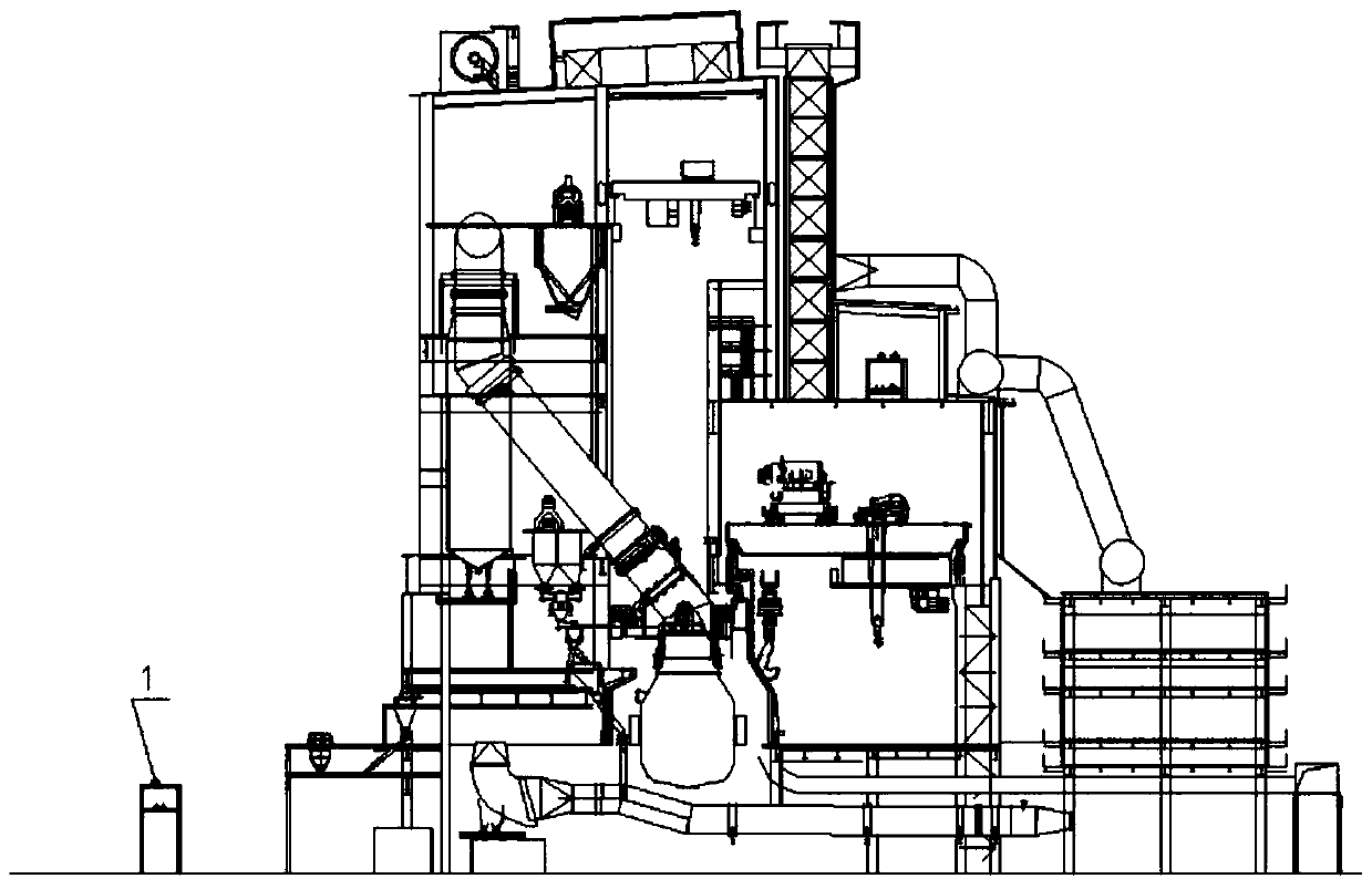
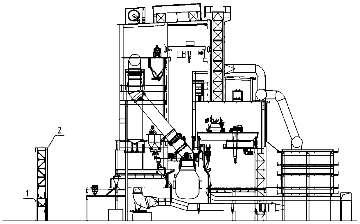
[0028] In the expansion project of a 120t steelmaking converter plant in Shandong, the installation method of the plant expansion steel column at the existing pipeline was adopted to complete the installation of the plant expansion steel column.

[0029] (1): Project overview:

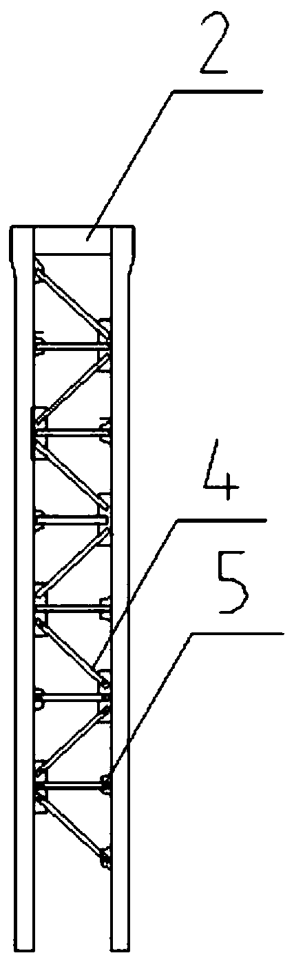
[0030] The relevant parameters of the expanded plant structure are: the maximum elevation of the latticed steel column of the expanded plant is 38.900m, the weight of the lower steel column 2 of the steel column is 44t, and the length is 27.400m; the weight of the upper steel column 3 is 14t, and the length is 12.500m m; Elevation dimension of the upper surface of the energy medium pipeline: the highest elevation is 10.000m, and the outer diameter of the energy medium pipeline is 273mm.

[0031] (2) The construction steps are:

[0032] Step 1, Screening of collision points for installation of steel columns for plant expansion: (such as figure 1 shown):

[0033] 1) According to the longitudinal and t...


PUM


Abstract

The invention discloses an installing method for factory building extension steel columns at an existing pipeline, and belongs to an installing method for steel structures of factory building extension. The method is characterized in that the steel columns of an extended factory building are divided into upper steel columns and lower steel columns, for column internal supports, inside the lower steel columns, located at the colliding positions of the energy medium pipeline, welding connection is changed into bolt connection, the lower segments of the lower steel columns are provided with n-shaped through grooves, when the lower steel columns are installed, the column internal supports are disassembled at first, then the lower steel columns are inserted downwards in the upper direction of the energy medium pipeline, stride the energy medium pipeline in the mode of bestriding, and then are inserted into a cup rabbet foundation, and after the lower steel columns are installed, the upper steel columns are installed. The method includes the construction steps that 1, installing colliding points of the factory building extension steel columns are sieved; 2, structural design is performedon the steel columns at the colliding points of factory building extension; 3, the steel columns at the colliding points of factory building extension are installed. With the method, the problem is solved that the production energy medium pipeline collides with the steel columns of factory building extension in the process of installation, and costs are lowered.

Description

technical field [0001] The invention belongs to a steel structure installation method for factory building extension, in particular to a method for installing a factory building extension steel column. Background technique [0002] In metallurgical engineering, it is often encountered that due to the owner's initial construction scale or the initial investment capital limitation, the original production workshop space is often insufficient when the subsequent production line process is transformed or the production scale is increased. The current solution to this problem The main way is to expand the original factory building. However, in the original production workshop, in order to meet the needs of producing energy medium, according to the conventional design, the production of energy medium was transported from the energy medium pipeline outside the plant to each production user point through the medium pipe network in the workshop; while most of the plant expansion, Ge...

Claims


Application Information

Patent Timeline
Patent Type & Authority Patents(China)
IPC IPC(8): E04G23/02
CPCE04G23/0266
Inventor 朱道付王声刚戴先平郑治飞张俊郭建明
Owner CHINA MCC17 GRP
Why Eureka
Try Eureka