Dark field defect detection device for large-caliber ultra-precise surface and measurement method thereof

A defect detection, ultra-precise technology, applied in measurement devices, scattering characteristics measurement, optical testing flaws/defects, etc., can solve the problems of low efficiency of dark field imaging method, inability to automatically measure the overall surface, etc., to achieve simple structure and remarkable effect , The effect of wide adaptability of material types

Pending Publication Date: 2018-10-30
INST OF MACHINERY MFG TECH CHINA ACAD OF ENG PHYSICS
View PDF0 Cites 17 Cited by
  • Summary
  • Abstract
  • Description
  • Claims
  • Application Information

AI Technical Summary

Problems solved by technology

[0005] The technical problem to be solved by the present invention is: the existing dark-field imaging method has the problems of low efficiency and the inability to automatically measure the defects of the overall surface. To provide a dark-field defect detection device and measurement method for large-caliber ultra-precision surfaces, which can use

Method used


Image

  • Dark field defect detection device for large-caliber ultra-precise surface and measurement method thereof
  • Dark field defect detection device for large-caliber ultra-precise surface and measurement method thereof
  • Dark field defect detection device for large-caliber ultra-precise surface and measurement method thereof

Examples


Embodiment 1

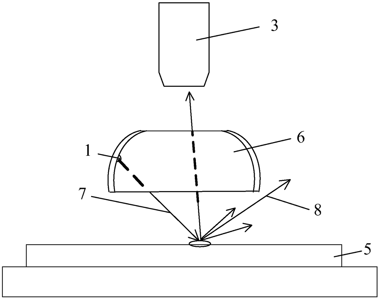
[0031] A dark-field defect detection device for large-diameter ultra-precision surfaces, such as figure 1 As shown, it is used to detect the sample to be tested of opaque material, and the sample to be tested is a large-caliber ultra-precision surface.

[0032] The detection device of the present invention includes: a light source 1, a sample holder for placing a sample to be tested 5, an imaging microscope 3 and a dome cover 6, such as figure 1 shown.

[0033] In the present invention, the light source 1 is arranged in the dome cover 6 , the sample to be tested 5 is fixed on the sample holder, the imaging microscope 3 is located above the sample to be tested 5 , and the dome cover 6 is located between the sample to be tested 5 and the imaging microscope 3 .

[0034] When in use, turn on the light source 1, adjust the height of the light source 1 so that the illumination light 7 emitted by the light source 1 obliquely irradiates the sample 5 to be tested, and the main reflect...

Embodiment 2

[0038] The difference between this embodiment and Embodiment 1 is that this embodiment further optimizes the setting of the structure of each part, which can effectively improve the detection effect. The specific settings are as follows:

[0039] First, the setting of the light source 1 is optimized. In the present invention, the illumination light 7 emitted by the light source 1 is preferably white or blue. Secondly, the setting between the imaging microscope 3 and the dome cover 6 is optimized, that is, the aperture size of the imaging microscope 3 is smaller than the aperture size of the top opening of the dome cover 6 .

[0040] Example 2

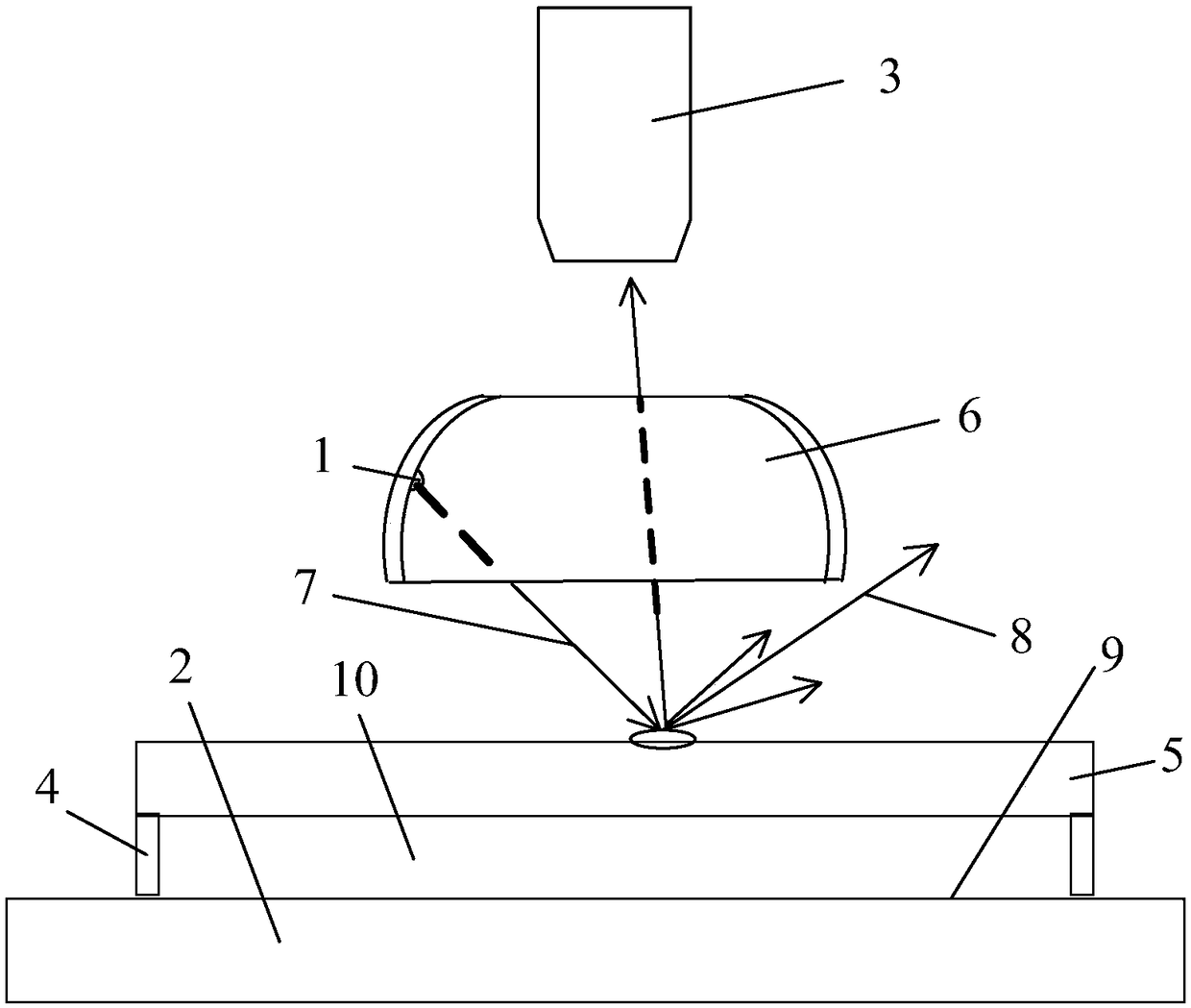
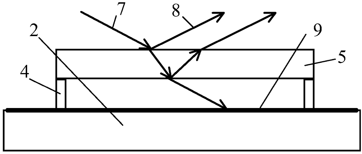
[0041] The difference between this embodiment and Embodiment 1 is that the structure of the sample holder is optimized in this embodiment, which is effectively suitable for testing samples of transparent materials, that is, it is suitable for large-caliber ultra-precision components with transparent surfaces, and the specific settings a...


PUM


Abstract

The invention discloses a dark field defect detection device for a large-caliber ultra-precise surface and a measurement method thereof. According to the device and the method, the problems that the efficiency is low, and the integral surface defects cannot be automatically measured in an existing dark field imaging method are solved. The device comprises a light source, a sample fixing frame andan imaging microscope, wherein the imaging microscope is located above the sample fixing frame and is arranged vertical to a to-be-measured surface of a to-be-measured sample; a dome cover with an opening in the top end is arranged between the sample fixing frame and the imaging microscope; and the light source is fixed on the inner side wall of the dome cover, illumination light emitted by the light source is obliquely emitted to the to-be-measured sample, main reflection light on the to-be-measured sample is reflected to the outer side of the dome cover, and scattered light on the to-be-measured sample enters the imaging microscope through the opening in the top end of the dome cover. The dark field defect detection device has the advantages of simple structure, high image contrast, widematerial type adaptability and the like, and the full-field automatic measurement is realized.

Description

technical field [0001] The invention relates to the field of material detection, in particular to a dark-field defect detection device for large-diameter ultra-precision surfaces and a measurement method thereof. Background technique [0002] During the cutting, grinding, polishing and cleaning process of metal components or optical components, various defects will inevitably occur on the surface of the material, and these defects will largely affect the performance of various components. [0003] The dark field imaging method has the characteristics of simple device, fast measurement speed and high certainty, and is widely used in the detection of surface defects. The principle is: the camera is perpendicular to the sample to be tested, and the lighting source illuminates the surface of the sample at a specific lighting angle. When there is no defect on the surface of the sample, the light emitted by the light source is reflected by the sample mirror, and no light enters t...

Claims


Application Information

Patent Timeline
IPC IPC(8): G01N21/88G01N21/47
CPCG01N21/47G01N21/8806G01N2021/8809G01N2021/4735
Inventor 李璐璐刘乾黄文
Owner INST OF MACHINERY MFG TECH CHINA ACAD OF ENG PHYSICS
Why Eureka
Try Eureka