Water source heat pump system

A technology of water source heat pump and heat source side, which is applied in lighting and heating equipment, refrigeration components, mechanical equipment, etc., and can solve problems such as inability to evaporate temperature and improve system energy efficiency

Pending Publication Date: 2018-02-13
上海中金能源投资有限公司
View PDF1 Cites 2 Cited by
  • Summary
  • Abstract
  • Description
  • Claims
  • Application Information

AI Technical Summary

Problems solved by technology

For specific user needs and heat sources, the water temperature at the outlet of the condenser and the water temperature at the outlet of the evaporator determine the limits of the condensing temperature and the evaporating temperature. At this time, it is impossible to improve the energy efficiency of the system by increasing the evaporating temperature and reducing the condensing temperature.

Method used


Image

  • Water source heat pump system

Examples


Embodiment 1

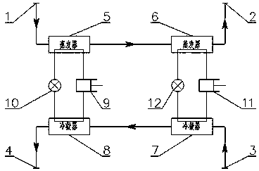
[0034] Such as figure 1 As shown, the water source heat pump system includes a primary evaporator 5, a secondary evaporator 6, a primary condenser 7, a secondary condenser 8, a first compressor 9, a second compressor 11, a first expansion valve 10 and a second Two expansion valves 12;

[0035] The primary evaporator 5 and the secondary evaporator 6 are arranged between the water inlet 1 on the heat source side and the water outlet 2 on the heat source side;

[0036] The water inlet of the primary evaporator 5 is connected to the heat source side water inlet 1 through a pipeline, and the water outlet is connected to the water inlet of the secondary evaporator 6 through a pipeline;

[0037] The water outlet of the secondary evaporator 6 is connected to the heat source side water outlet 2 through a pipeline;

[0038] The primary condenser 7 and the secondary condenser 8 are arranged between the user-side water inlet 3 and the user-side water outlet 4;

[0039] The water inlet ...

Embodiment 2

[0047] Based on the water source heat pump system of Embodiment 1, the first compressor 9 and the first expansion valve 10 connected by pipelines between the primary evaporator 5 and the secondary condenser 8 form the first heat pump cycle system; the secondary evaporator 6 A second compressor 11 and a second expansion valve 12 communicated with the primary condenser 7 form a second heat pump cycle system;

[0048] N evaporators are also connected in series between the primary evaporator 5 and the secondary evaporator 6, and N condensers are also connected in series between the primary condenser 7 and the secondary condenser 8. The N evaporators and the N The condensers are in one-to-one correspondence with a compressor and an expansion valve connected through pipelines to form N heat pump circulation systems, where N is a positive integer.

Embodiment 3

[0050] Based on the water source heat pump system of Embodiment 1, the water inlet 1 on the heat source side communicates with mid-deep geothermal water, and the mid-deep geothermal water is used as heat source water.

[0051] In the water source heat pump system of Embodiment 3, the medium-deep geothermal water at 40°C enters the water inlet on the heat source side and first flows through the primary evaporator 5 to drop to 30°C, then flows through the secondary evaporator 6 to drop to 20°C, and then flows from the heat source The side water outlet flows out; the user-side water at 45°C enters the user-side water inlet, first flows through the primary condenser 7 and is heated to 50°C, then flows through the secondary condenser 8 and is heated to 55°C, and then flows out from the user-side water outlet.


PUM


Abstract

The invention discloses a water source heat pump system. A first level evaporator and a second level evaporator are arranged between a heat source side water inlet and a heat source side water outlet,a first level condenser and a second level condenser are arranged between a user side water inlet and a user side water outlet, and a first compressor is communicated with a first expansion valve through a pipeline to form a first heat pump circulatory system between the first level evaporator and the second level condenser; a second compressor is communicated with a second expansion valve through a pipeline to form a second heat pump circulatory system between the second level evaporator and the first level condenser. Compared with a single circulating heat pump system, the water source heatpump system is high in energy efficiency, capable of achieving running of a heat source side with a big temperature difference more easily and reducing the energy consumption of an transmission and distribution system, and wide in application range of high-temperature heat sources.

Description

technical field [0001] The invention relates to HVAC equipment technology, in particular to a water source heat pump system. Background technique [0002] A compression heat pump system usually consists of four basic components: a compressor, an evaporator, a condenser, and a throttle valve. The above components are connected in sequence through pipelines to form a complete heat pump system. The refrigerant circulates continuously in the system and changes its state. And exchange heat with the outside to achieve the purpose of cooling or heating. [0003] Theoretically speaking, the energy efficiency of a heat pump system mainly depends on the condensation temperature and evaporation temperature: the lower the condensation temperature, the higher the evaporation temperature, and the higher the energy efficiency of the system; the higher the condensation temperature, the lower the evaporation temperature, and the lower the energy efficiency of the system. For specific user n...

Claims


Application Information

Patent Timeline
Patent Type & Authority Applications(China)
IPC IPC(8): F25B1/00F25B41/00F25B41/40
CPCF25B1/00F25B2400/06F25B41/40
Inventor 陈永平王重超周聪陈军
Owner 上海中金能源投资有限公司
Why Eureka
Try Eureka