
Face identification attendance equipment

A face recognition and equipment technology, applied in character and pattern recognition, electrical equipment structural parts, electrical equipment shells/cabinets/drawers, etc. Improve stability, high precision, and not easy to scratch

Inactive Publication Date: 2018-10-30
广州泰沃技术有限公司
View PDF4 Cites 0 Cited by
  • Summary
  • Abstract
  • Description
  • Claims
  • Application Information

AI Technical Summary

Problems solved by technology

[0002] In the existing technology, whether it is for work or for students to go to class, they must sign in. Among the many sign-in methods, face recognition sign-in is the most accurate, so more and more companies start to use face recognition sign-in equipment, but Since the height of each person is different, after the device is fixed on the wall, when a person who is too tall or too short checks in, he needs to use some methods to change the height difference between the face and the device, which is a waste of time and looks awkward. In the existing technology, the equipment is easily contaminated with dust during use, and if it is not cleaned in time, it will cause errors in the accuracy of the equipment, and manual scrubbing will cause scratches on the body and shorten the service life of the equipment. In the prior art, there are many parts that make up the body , and are all wrapped in a small space by the shell, choosing internal heat dissipation will cause dust to be adsorbed on the fan, so that a lot of dust will enter the inside of the body, and the internal space is narrow and very difficult to clean, affecting the service life of the equipment, so a human face is needed Identify check-in devices to solve the problems mentioned above

Method used


Image

  • Face identification attendance equipment
  • Face identification attendance equipment
  • Face identification attendance equipment

Examples


Embodiment Construction

[0020] In order to make the technical means, creative features, goals and effects achieved by the present invention easy to understand, the present invention will be further described below in conjunction with specific embodiments.

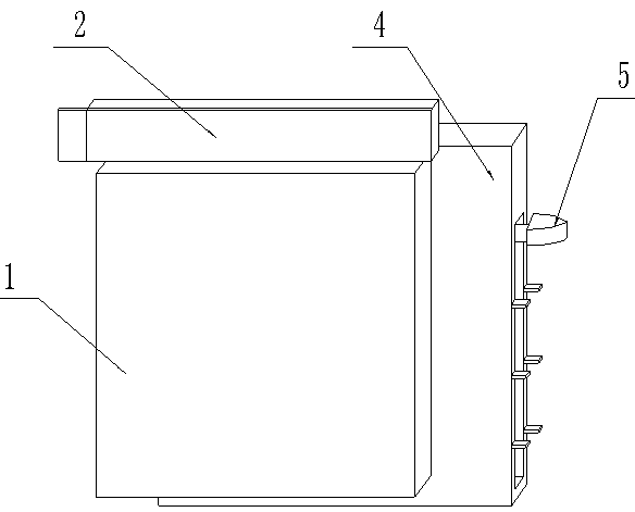
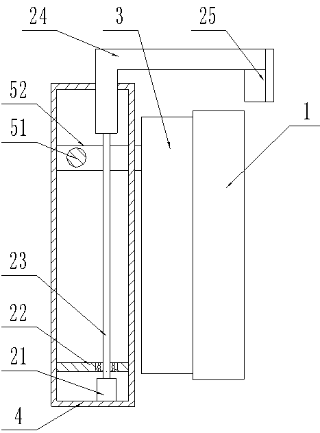
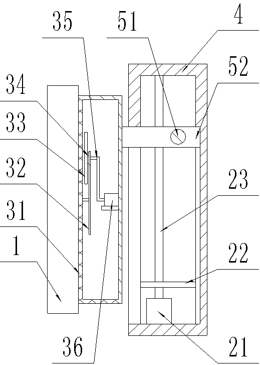
[0021] see Figure 1-Figure 4 , the present invention provides a technical solution: a face recognition sign-in device, including a body 1, a cleaning device 2, a cooling device 3, a fixed cover 4 and a moving device 5, the rear end of the fixed cover 4 is fixed on the wall, and the cleaning device 2 is installed at the left end of the fixed cover 4, the mobile device 5 is installed at the right end of the fixed cover 4, the heat sink 3 is connected to the front side of the fixed cover 4, and the body 1 is fixed at the front end of the heat sink 3.

[0022] The cleaning device 2 includes a small motor 21, a support plate 22, a screw mandrel 23, a connecting frame 24, a cotton brush 25 and a ball nut seat 26, and the left side of the fixed cover 4 ...


PUM


Abstract

The invention provides a face identification attendance equipment, which comprises a machine body, a fixed cover, a lead screw, a connecting frame, a cotton brush, a ball nut seat, an outer cover, a fan, a pinion, a connecting shaft, a long spindle and a rotary handle, wherein the upper end of the lead screw is installed in a first round groove; the ball nut seat is installed on the annular side surface of the lead screw; the rear end of the connecting frame is connected to the left end of the annular side surface of the ball nut seat; and the rear end of the rear side surface of the cotton brush is installed on the front end of the connecting frame. By use of the design, the function that dust and moisture on the surface of the machine body can be cleaned is realized, the front end of theconnecting shaft is connected with the rear end of the pinion, and the fan is installed on the front end of the pinion. By use of the design, timely cooling in a machine body operation process is realized, the left end of the long spindle penetrates through a through and a second square hole and extends to the left side of the fixed cover, and the right end and the left end of the long spindle are connected with the rotary handle. The vertical movement function of the machine body is realized, and the equipment has the advantages of flexible structure, high accuracy, good stability and convenience in use.

Description

technical field [0001] The invention relates to a face recognition sign-in device, which belongs to the field of intelligent recognition devices. Background technique [0002] In the existing technology, whether it is for work or for students to go to class, they must sign in. Among the many sign-in methods, face recognition sign-in is the most accurate, so more and more companies start to use face recognition sign-in equipment, but Since the height of each person is different, after the device is fixed on the wall, when a person who is too tall or too short checks in, he needs to use some methods to change the height difference between the face and the device, which is a waste of time and looks awkward. In the existing technology, the equipment is easily contaminated with dust during use, and if it is not cleaned in time, it will cause errors in the accuracy of the equipment, and manual scrubbing will cause scratches on the body and shorten the service life of the equipment...

Claims


Application Information

Patent Timeline
Patent Type & Authority Applications(China)
IPC IPC(8): G06K9/00G07C1/10B08B1/00H05K7/20H05K5/02
CPCH05K5/0217H05K5/023H05K7/20172G07C1/10G06V40/161B08B1/30B08B1/12
Inventor 颜臣龙林辉
Owner 广州泰沃技术有限公司
Learn More