Plate wing machine with upper and lower wings

A slat-wing aircraft and double-wing technology, which is applied in the aviation field, can solve the problems of divergence and insufficient rigidity of the wing structure of the slat-wing aircraft, and achieve the effects of improving structural rigidity, eliminating mutual interference and improving lift.

Inactive Publication Date: 2018-11-02
KUNMING QIAOYI SCI & TECH CO LTD
View PDF6 Cites 2 Cited by
  • Summary
  • Abstract
  • Description
  • Claims
  • Application Information

AI Technical Summary

Problems solved by technology

[0005] The technical problem to be solved in the present invention is to propose a flat-wing aircraft with upper and lower wings in order to overcome the shortcomings of insufficient rigidity of the wing structure of the flat-wing aircraft and the divergence of the chord-wise blowing airflow, so that the wings of the flat-wing aircraft are more compact, stable and reasonable , efficient

Method used


Image

  • Plate wing machine with upper and lower wings
  • Plate wing machine with upper and lower wings
  • Plate wing machine with upper and lower wings

Examples


Embodiment 1

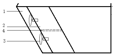
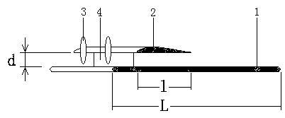
[0026] Embodiment 1: as Figure 1-3As shown, the plate-wing aircraft with upper and lower wings comprises a fuselage, wings, power structure and control mechanism, and the wings of the plate-wing aircraft are flat airfoil wings. The top of the upper wing is provided with the upper wing 2 of the convex lower flat airfoil, the lower wing 1 is the main wing, and the upper wing 2 is the aileron. Two vertical spoilers 4 are arranged between the two parallel surfaces of the upper and lower wing plates. Two adjacent vertical spoilers form a rectangular box with the upper surface of the lower wing and the lower surface of the upper wing, which rectifies the airflow blown out by the driving mechanism, enhances the structural rigidity of the wing and provides convenience for the installation of the driving device; Four small propeller drive devices 3 are arranged in the middle of the front edge of the upper wing 2, and the height distance between the upper wing and the lower wing is con...

Embodiment 2

[0029] Example 2: see Figure 1-3 , the plate-wing aircraft with upper and lower wings includes a fuselage, wings, power structure and control mechanism. There is an upper wing 2 with an upper convex lower flat airfoil, the lower wing 1 is the main wing, and the upper wing 2 is the aileron. Four vertical spoilers 4 are arranged between the two parallel surfaces of the upper and lower wing plates. The adjacent vertical spoiler forms a rectangular box with the upper surface of the lower wing and the lower surface of the upper wing, which rectifies the airflow blown out by the drive mechanism, enhances the structural rigidity of the wing and facilitates the installation of the drive device; the upper wing 2. There are 10 small-sized turbojet engine driving devices 3 arranged in the middle of the front edge, and the height distance between the upper wing and the lower wing is controlled to be greater than the radius of the turbojet engine air inlet by 3 cm. The position of the dri...

Embodiment 3

[0032] Embodiment 3: see Figure 1-3 , the plate-wing aircraft with upper and lower wings includes a fuselage, wings, power structure and control mechanism. There is an upper wing 2 with an upper convex lower flat airfoil, the lower wing 1 is the main wing, and the upper wing 2 is the aileron. Four vertical spoilers 4 are arranged between the two parallel surfaces of the upper and lower wing plates. The adjacent vertical spoiler forms a rectangular box with the upper surface of the lower wing and the lower surface of the upper wing, which rectifies the airflow blown out by the drive mechanism, enhances the structural rigidity of the wing and facilitates the installation of the drive device; the upper wing The middle part of the leading edge of 2 is arranged with 6 small turbojet engine driving devices 3, and the height distance between the upper wing and the lower wing is controlled to be greater than the radius of the turbojet engine air inlet by 2 cm, and the position of the...


PUM


Abstract

The invention discloses a plate wing machine with upper and lower wings and belongs to the technical field of aviation. The plate wing machine comprises a body, wings, a power mechanism and an operating mechanism, wherein the plate wing machine is provided with upper and lower wings, the lower wing is a flat plate wing type machine wing, an upper convex and lower flat wing type upper wing is arranged above the lower wing, a plurality of driving devices are arranged in parallel in the middle of the front edge of the upper wing, the height distance between the upper and lower wings is slightly greater than the radius of a propeller or a fumaroles of each driving device, the propeller or the fumaroles of each driving device blows a high speed air flow chordwise due to the position of each driving device to equally divide the air flow to upper and lower surfaces of the upper wing, so that the upper half part of air flow can quickly flow through the upper surface of the upper wing, and meanwhile, the lower half part of air flow flows through a box body formed by encircling of the lower surface of the upper wing and the upper surface of the flat plate wing uniformly. The plate wing machine has the advantages of fully exerting the pneumatic efficiency of upper and lower wings, being reasonable in structure, reliable to work, safe and stable, low in cost, high in flight efficiency andthe like.

Description

technical field [0001] The invention relates to a method for improving the flight efficiency of an aircraft and the rigidity of the wing structure, in particular to a board-wing aircraft with upper and lower wings, which belongs to the field of aviation technology. Background technique [0002] Manned aircraft can be divided into two categories: fixed wing and rotary wing. Fixed wing is commonly used in horizontal take-off and landing aircraft (such as jet airliners), while rotary wing is commonly used in vertical take-off and landing aircraft (such as helicopters). As far as the current technical level is concerned, fixed-wing aircraft can fly at high speed and are easy to operate, but they need to rely on runways to take off and land. Rotary wing aircraft can take off and land vertically without relying on runways, and has strong adaptability, but the mechanism is out of balance, the control is complicated, the flight speed is slow, and the fuel efficiency is low. [0003...

Claims


Application Information

Patent Timeline
Patent Type & Authority Applications(China)
IPC IPC(8): B64C39/08B64C3/14
CPCB64C39/08B64C3/14
Inventor 杨卫华
Owner KUNMING QIAOYI SCI & TECH CO LTD
Why Eureka
Try Eureka