Electromagnetic upcast microgravity device and control method thereof and electromagnetic upcast microgravity system

A technology of microgravity and electromagnetic braking, which is applied to the simulation device of space navigation conditions, transportation and packaging, space navigation equipment, etc., can solve the problems of low utilization rate of stroke efficiency, short time of microgravity, and short stroke, etc. Efficiency, to achieve the effect of full control

Active Publication Date: 2018-11-02
TECH & ENG CENT FOR SPACE UTILIZATION CHINESE ACAD OF SCI
View PDF5 Cites 9 Cited by
  • Summary
  • Abstract
  • Description
  • Claims
  • Application Information

AI Technical Summary

Problems solved by technology

Several methods have their own advantages and disadvantages: sounding rockets have the longest time, but the launch cost is too high, no less than microgravity satellites; weightless aircraft can provide more than 20 seconds of microgravity time, and can carry larger loads, but microgravity The level is up to 10-3g, which is also relatively expensive; if the drop tower adopts a double cabin method, it can reach the order of 10-5~10-6, but the microgravity time is too short
Chemical energy explosive ejection and steam energy ejection can provide greater force, but the utilization rate of stroke efficiency is low and the controllability is poor; hydraulic energy can use the hydraulic cylinder with low acceleration of the pulley transmission mechanism, and the straight-top high-speed hydraulic Cylinder solution, but the stroke is relatively short; using direct drive motor for traction, the requirements for the conveyor belt are too high when the distance is relatively long, and the output force provided is relatively small

Method used


Image

  • Electromagnetic upcast microgravity device and control method thereof and electromagnetic upcast microgravity system
  • Electromagnetic upcast microgravity device and control method thereof and electromagnetic upcast microgravity system
  • Electromagnetic upcast microgravity device and control method thereof and electromagnetic upcast microgravity system

Examples


no. 1 example

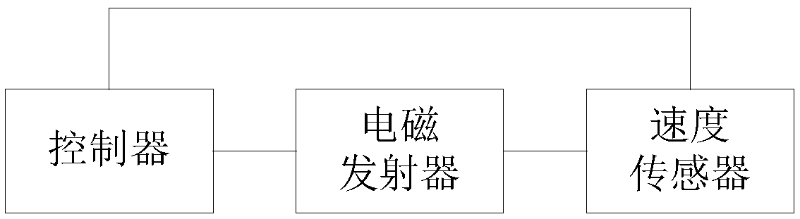
[0038] See figure 1 , figure 1 This is a schematic structural diagram of an electromagnetic upward throwing microgravity device provided by an embodiment of the present invention.

[0039] Such as figure 1 As shown, the device includes an electromagnetic transmitter, a speed sensor and a controller, where

[0040] The speed sensor is used to monitor the speed of the electromagnetic transmitter, obtain the operating speed, and transmit the operating speed to the controller, where the operating speed includes the first operating speed and the second operating speed.

[0041] During the operation of the electromagnetic upward throwing microgravity device, the speed sensor monitors the operating speed of the electromagnetic transmitter. It can be understood that when the electromagnetic transmitter is in motion, the electromagnetic transmitter and the payload bay can handle different stages or modes. Such as: static mode before launch, launch mode during launch, and free fall motion mod...

no. 2 example

[0059] This embodiment is based on the first embodiment.

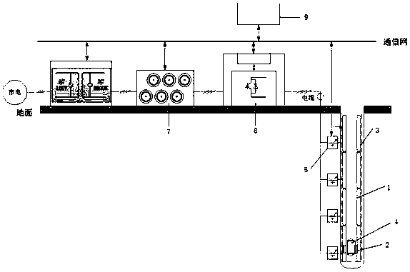
[0060] See figure 2 , figure 2 This is a schematic structural diagram of an electromagnetic upward throwing microgravity system provided by an embodiment of the present invention.

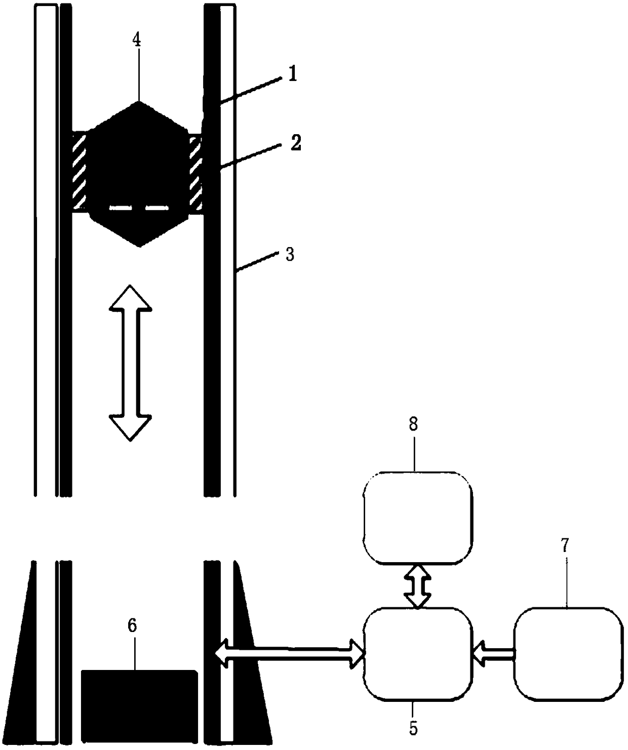
[0061] Combine figure 1 with figure 2 , The device also includes: a guide rail 3, the electromagnetic transmitter includes: a mover 2 and a stator 1, wherein,

[0062] The guide rail 3 is used to fix the stator 1 so that the stator 1 is fixedly installed on the guide rail 3.

[0063] The speed sensor is specifically used to monitor the speed of the mover 2.

[0064] The speed sensor specifically monitors the speed of the mover 2 in the electromagnetic transmitter to obtain the operating speed.

[0065] The controller is specifically used to: control the mover 2 to carry the payload bay 4 to launch.

[0066] When the controller controls the electromagnetic transmitter to carry the payload bay 4 to launch, specifically, it controls the mover 2 to carr...

no. 3 example

[0071] This embodiment is based on the second embodiment. Please keep reading figure 2 .

[0072] The device also includes: a position sensor and a switch 5, wherein,

[0073] The position sensor is used to monitor the position of the mover 2 and send the monitored position information to the controller.

[0074] Since the movement of the electromagnetic transmitter is the movement of the mover, the position of the mover 2 will change. The position of the mover 2 is monitored by using a position sensor.

[0075] When the mover 2 is in the first section of the guide rail, and the controller determines according to the received position information that the distance between the mover 2 and the second section of the guide rail is less than or equal to the preset distance threshold, the controller is used to: turn on the switch 5, In order to power the electromagnetic transmitter through the switch 5.

[0076] Among them, the first section of the guide rail and the second section of the...


PUM


Abstract

An embodiment of the invention relates to an electromagnetic upcast microgravity device and a control method thereof and an electromagnetic upcast microgravity system, wherein the electromagnetic upcast microgravity device comprises an electromagnetic launcher, a speed sensor and a controller, wherein the speed sensor is used for monitoring speed of the electromagnetic launcher to obtain operatingspeed and transmitting the operating speed to the controller, and the controller is used for comparing the first operating speed received, to a first speed threshold preset, and controlling the electromagnetic launcher to launch with a load module; when the electromagnetic launcher with the load module is in free-falling motion, the controller is also used for comparing second operating speed with a second speed threshold preset, and producing braking force for the electromagnetic launcher, when the second operating speed is equal to the second speed threshold, to control the electromagneticlauncher to enter an electromagnetic braking decelerating mode. Upcast launching is performed in electromagnetic force mode; therefore, efficiency is improved, and full-process control is achieved.

Description

Technical field [0001] The embodiment of the present invention relates to the technical field of design space, in particular to an electromagnetic upward throwing microgravity device, a control method and a system. Background technique [0002] It is understandable that there are two application requirements for ground microgravity simulation: first, for space microgravity science. Microgravity science includes many disciplines such as space life, microgravity fluid physics, microgravity combustion, space materials, and basic physics, as well as new technology experiments in space in many fields. Scientific experiment satellites, space laboratories, and space stations are used as experimental platforms for long-term operation in orbit, which can provide a high level of microgravity, but the development requirements are high, the cost is high, and the opportunities are scarce. Many experiments can obtain valid experimental results through short-term microgravity environments, and...

Claims


Application Information

Patent Timeline
Patent Type & Authority Applications(China)
IPC IPC(8): B64G7/00
CPCB64G7/00
Inventor 张善从李雨蔓董文博张建泉席隆李响张永康白亮宇乔志宏
Owner TECH & ENG CENT FOR SPACE UTILIZATION CHINESE ACAD OF SCI
Why Eureka
Try Eureka