Gas mixing structure, process chamber and semiconductor processing equipment

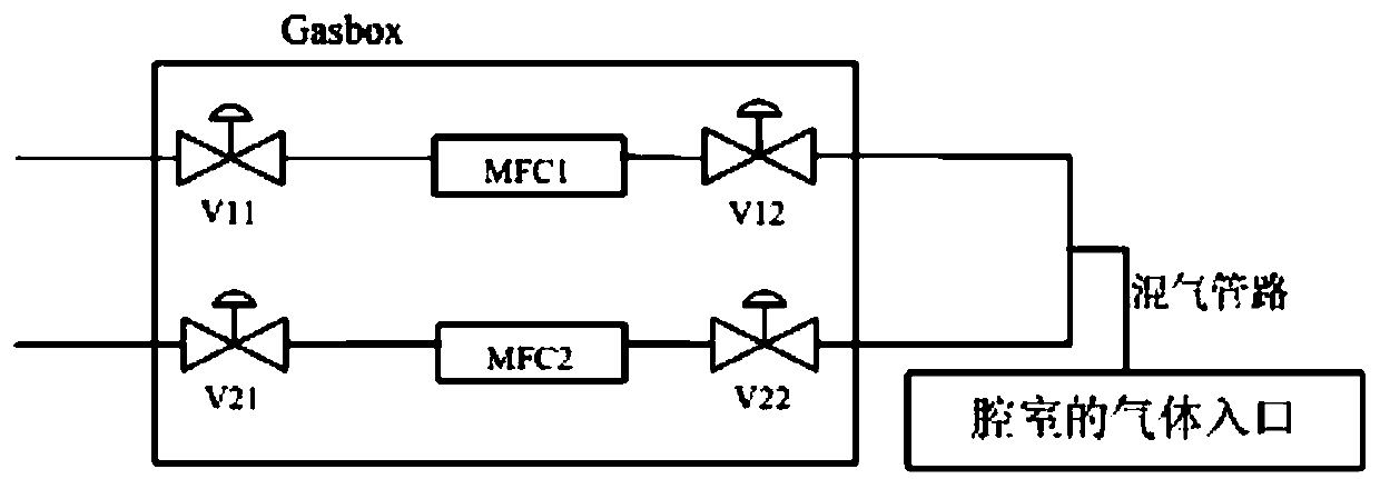
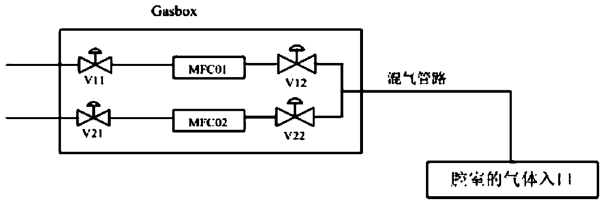
A gas mixing and gas technology, applied in metal material coating process, gaseous chemical plating, coating and other directions, can solve the problems of blocked pipelines, easy to generate deposits, short gas mixing pipelines, etc., to reduce the length, gas, etc. well-mixed effect

Active Publication Date: 2020-06-19
BEIJING NAURA MICROELECTRONICS EQUIP CO LTD
View PDF5 Cites 0 Cited by
  • Summary
  • Abstract
  • Description
  • Claims
  • Application Information

AI Technical Summary

Problems solved by technology

[0006] First, use figure 1 In the gas mixing structure shown, because the gas mixing pipeline is short, the gas is mixed unevenly in a very short pipeline
[0007] Second, use figure 2 The mixed gas structure shown, the relative figure 1 Although the length of the gas mixing pipeline has improved to a certain extent the problem of uneven gas mixing, it is easy to generate deposits and block the pipeline when mixing in a long pipeline.

Method used


Image

  • Gas mixing structure, process chamber and semiconductor processing equipment
  • Gas mixing structure, process chamber and semiconductor processing equipment
  • Gas mixing structure, process chamber and semiconductor processing equipment

Examples


Embodiment 1

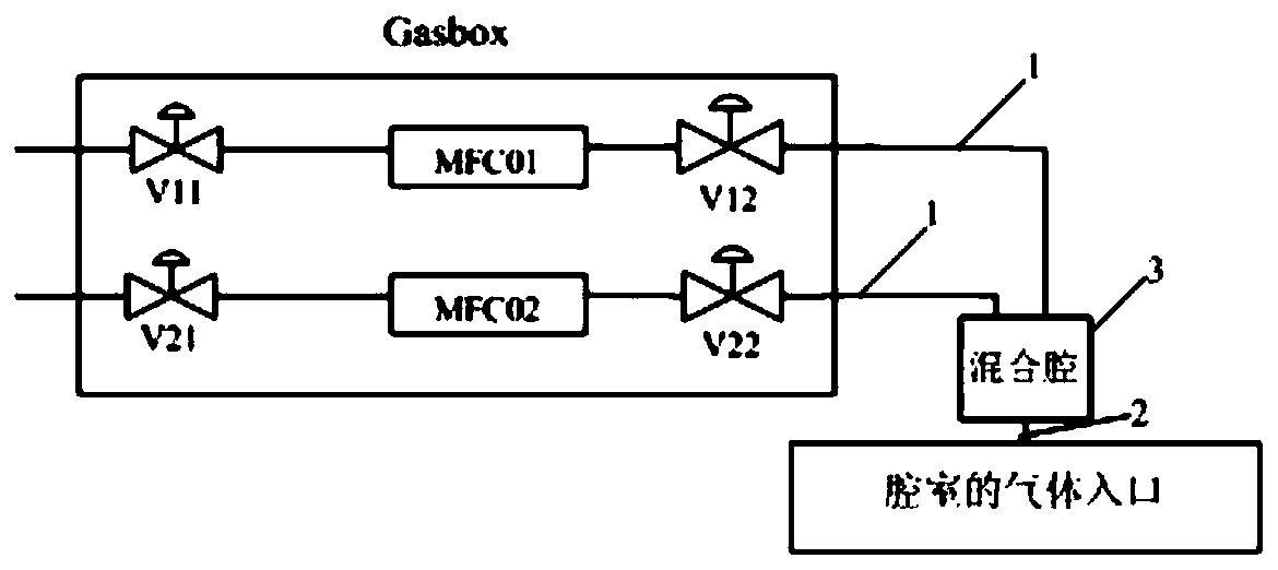
[0044] image 3 This is a schematic structural diagram of a gas mixing structure provided by an embodiment of the present invention; please refer to image 3 , The gas mixing structure provided by the embodiment of the present invention is used to provide gas to the chamber, and includes a multi-channel gas inlet pipe 1 and at least one gas outlet pipe 2. The multi-channel gas inlet pipe 1 is connected to multiple gas sources one by one, The gas outlet pipe 2 is connected to the gas inlet of the chamber. The gas mixing structure further includes a mixing chamber 3, which has a gas mixing space, and the mixing chamber 3 is respectively connected with the gas inlet pipe 1 and the gas outlet pipe 2 for mixing the gases from multiple gas sources in the gas mixing space Then it is output to the gas inlet of the chamber through the gas outlet pipe 2.

[0045] Wherein, the number of air intake pipes 1 included in the air mixing structure can be set as required. For example, the air mixi...

Embodiment 2

[0059] The embodiment of the present invention provides a process chamber including a gas mixing structure for mixing different gases before entering the chamber. The gas mixing structure adopts the gas mixing structure in Embodiment 1.

[0060] The process chamber provided by the embodiment of the present invention adopts the gas mixing structure in Example 1, so the process chamber can not only make the gas mixed more evenly, but also does not block the pipeline, thereby improving the process of the process chamber. The quality and stability and reliability of the chamber.

Embodiment 3

[0062] The embodiment of the present invention provides a semiconductor processing equipment including a process chamber, and the process chamber adopts the process chamber in the above-mentioned embodiment 2.

[0063] The semiconductor processing equipment provided by the embodiments of the present invention adopts the process chamber provided in the above-mentioned embodiment 2 of the present invention, and therefore, the process quality, stability and reliability of the semiconductor processing equipment can be improved.


PUM


Abstract

The invention provides a gas mixing structure. The gas mixing structure is used for providing gas for a chamber and comprises multiple gas inlet pipelines and at least one gas outlet pipeline. The multiple gas inlet pipelines and multiple gas sources are in one-to-one correspondence connection, and the gas outlet pipeline is connected with a gas inlet of the chamber. A mixing cavity is further included and has a gas mixing space, and the mixing cavity is connected with the gas inlet pipelines and the gas outlet pipeline and is used for enabling gas of the multiple gas sources to be mixed in the gas mixing space and then output to the gas inlet of the chamber through the gas outlet pipeline. The invention further provides the process chamber and a semiconductor processing equipment. According to the gas mixing structure, the process chamber and the semiconductor processing equipment, the gas can be mixed to be uniform, and the pipelines cannot be blocked.

Description

Technical field [0001] The invention belongs to the technical field of microelectronics processing, and specifically relates to a gas mixing structure, a process chamber and semiconductor processing equipment. Background technique [0002] LED PECVD equipment is mainly used to deposit and coat the surface of sapphire or silicon wafers, and deposit SiN / SiO on the surface of the wafer. The specific process is: usually SiH 4 With N 2 After O and other gases are mixed in proportions, they are passed into the reaction chamber, and then RF voltage is applied to initiate igniting excitation to form plasma, and finally SiN / SiO film is deposited on the wafer. It should be emphasized that gas mixing is one of the key steps before the LED PECVD reaction. Whether the gas mixing is sufficient will also determine whether the entire furnace film thickness and refractive index uniformity in a single furnace batch meet the requirements. [0003] figure 1 For a structural schematic diagram of a gas...

Claims


Application Information

Patent Timeline
Patent Type & Authority Patents(China)
IPC IPC(8): C23C16/455C23C16/40C23C16/34
CPCC23C16/345C23C16/401C23C16/45512
Inventor 王福来
Owner BEIJING NAURA MICROELECTRONICS EQUIP CO LTD
Why Eureka
Try Eureka