
Fluorescent immunoassay device and control method thereof

A fluorescence immunoassay and push-out device technology, which is applied in the field of fluorescence immunoassay devices and their control, can solve the problems of inability to realize the detection of quantity reagent cards, inability to realize miniaturization of the detection device, and large volume occupied by the feeding structure, and achieve a simple structure. , the effect of preventing jitter and improving the accuracy of results

Pending Publication Date: 2018-11-02
SHENZHEN LIVING WATER POCT CO LTD
View PDF5 Cites 2 Cited by
  • Summary
  • Abstract
  • Description
  • Claims
  • Application Information

AI Technical Summary

Problems solved by technology

[0002] In the prior art, when conducting biological detection, the circular incubating tank structure is generally used for detection. The disadvantage is that it occupies a large volume, and a linear incubating tank structure is also used to incubate the reagent card. However, due to the There are generally fixed partitions between the cards, resulting in a small number of incubated reagent cards and a large volume; when adding reagent cards for feeding, generally use the incubation tank to move a single feeding or use an array-like elevator structure Feeding is carried out in a different way, which leads to a large volume of the entire feeding structure, and leads to a complex heat dissipation structure of the incubation system
Such as the above-mentioned prior art, the overall volume of the existing detection device is large, and the miniaturization of the detection device cannot be realized, and the detection of a large number of reagent cards cannot be realized.

Method used


Image

  • Fluorescent immunoassay device and control method thereof
  • Fluorescent immunoassay device and control method thereof
  • Fluorescent immunoassay device and control method thereof

Examples


Embodiment Construction

[0045] In order to make the objectives, technical solutions and advantages of the present invention clearer, the present invention will be described in further detail below in conjunction with the accompanying drawings and their embodiments; it should be understood that the specific embodiments described here are only used to explain the present invention and are not intended to to limit the present invention. Other systems, methods and / or features of this embodiment will become apparent to those skilled in the art after reviewing the following detailed description. It is intended that all such additional systems, methods, features and advantages be included within this description, be within the scope of the invention, and be protected by the following claims. Additional features of the disclosed embodiments are described in, and will be apparent from, the following detailed description.

[0046] Such as figure 1 As shown, it is the overall structure diagram of the fluoresc...


PUM


Abstract

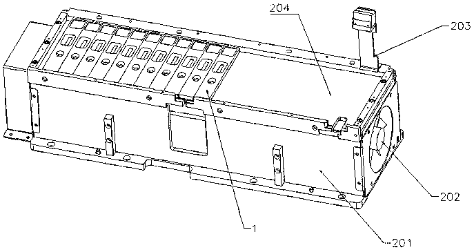
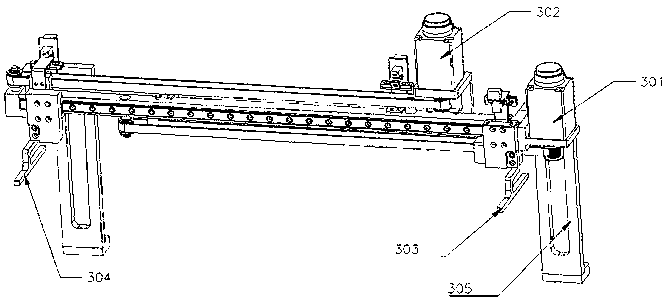
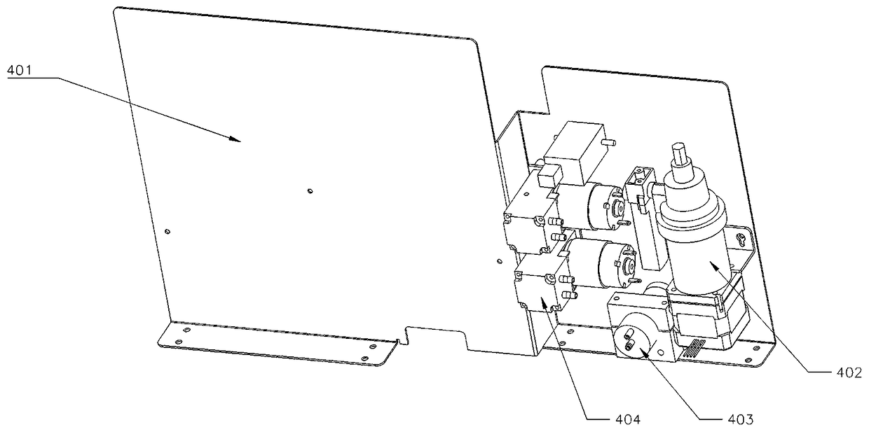
The invention discloses a fluorescent immunoassay device and control method thereof, including a base board, a reagent card propelling device (7), an incubation slot device (2) anda reagent card pushing-out device (9) are arranged on the base board, the reagent card propelling device (7) is perpendicular to the reagent card entry of the incubation slot device (2), the reagent card pushing-out device (9) is perpendicular to the reagent card exit of the incubation slot device (2), the incubation slot device (2) comprises an incubation slot panel (204), wherein an incubation slot surrounding edge is arranged around the incubation slot panel (204), the inside of the surrounding edge is provided with a flat structure without intervals, and the reagent card can move steplessly along the flat structure without intervals, the fluorescent immunoassay device provided by the invention can realize automatic sample addition and incubation of a plurality of reagent cards simultaneously, and testingin sequence according to the program setting, improving the detection efficiency and reducing the volume of the equipment.

Description

technical field [0001] The invention relates to the technical field of biological detection, in particular to a fluorescent immunoassay device and a control method thereof. Background technique [0002] In the prior art, when conducting biological detection, the circular incubating tank structure is generally used for detection. The disadvantage is that it occupies a large volume, and a linear incubating tank structure is also used to incubate the reagent card. However, due to the There are generally fixed partitions between the cards, resulting in a small number of incubated reagent cards and a large volume; when adding reagent cards for feeding, generally use the incubation tank to move a single feeding or use an array-like elevator structure Feeding is carried out in a different way, resulting in a larger volume of the entire feeding structure, and resulting in a complex heat dissipation structure of the incubation system. Such as the above-mentioned prior art, the overa...

Claims


Application Information

Patent Timeline
IPC IPC(8): G01N35/00G01N35/10
CPCG01N35/00G01N35/10
Inventor 王东元刘志刚武通园
Owner SHENZHEN LIVING WATER POCT CO LTD
Learn More