Flight path determining method for performing automatic inspection on fan through unmanned aerial vehicle and system thereof

A flight path and automatic inspection technology, which is applied in control/regulation systems, non-electric variable control, vehicle position/route/height control, etc., can solve problems such as large manpower and operator safety risks, and improve computing efficiency, The effect of convenient planning

Active Publication Date: 2018-11-02
SHANGHAI CLOBOTICS TECHNOLOGY CO LTD
View PDF12 Cites 28 Cited by
  • Summary
  • Abstract
  • Description
  • Claims
  • Application Information

AI Technical Summary

Problems solved by technology

[0004] At present, when detecting damage on the surface of the blade, it is usually used to manually climb up the wind turbine for detection, which not only consumes a lo

Method used


Image

  • Flight path determining method for performing automatic inspection on fan through unmanned aerial vehicle and system thereof
  • Flight path determining method for performing automatic inspection on fan through unmanned aerial vehicle and system thereof
  • Flight path determining method for performing automatic inspection on fan through unmanned aerial vehicle and system thereof

Examples


Embodiment Construction

[0075] The present invention will be described in detail below in conjunction with specific embodiments. The following examples will help those skilled in the art to further understand the present invention, but do not limit the present invention in any form. It should be noted that those skilled in the art can make several modifications and improvements without departing from the concept of the present invention. These all belong to the protection scope of the present invention.

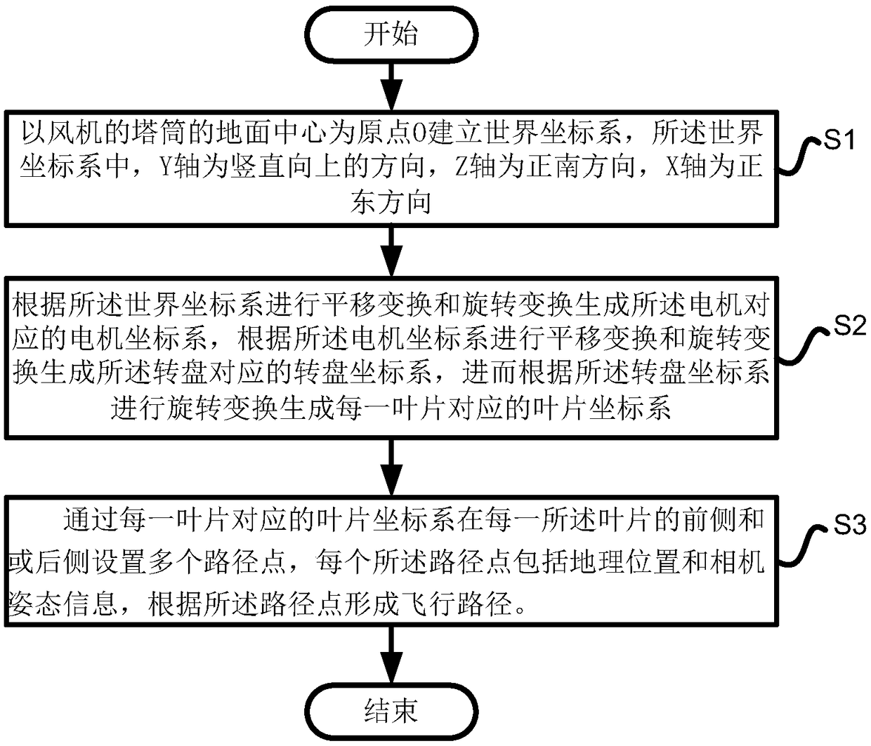
[0076] figure 1 In the present invention, it is a flow chart of the steps of the method for determining the flight path of automatic inspection of the fan by the unmanned aerial vehicle; as figure 1 As shown, the invention provides a method for determining the flight path of an automatic inspection of a wind turbine by an unmanned aerial vehicle. The wind turbine includes a wind tower, an impeller and a generator arranged at the top of the wind tower, and the impeller is arranged at the front end ...


PUM


Abstract

The invention provides a flight path determining method for performing automatic inspection on a fan through an unmanned aerial vehicle and a system thereof. The fan at least comprises a tower, a power generator, a wheel hub and an impeller. The impeller comprises a plurality of blades. The method comprises the steps of establishing a world coordinate system through using a ground center of the tower of the fan as an original O, wherein a Y axis is in a vertical direction, a Y axis is in a vertical upward direction, a Z axis is in a right north direction, and an X axis is a right east direction; performing translation transformation and rotation transformation according to the world coordinate system for generating a power generator coordinate system which corresponds with the power generator, performing translation transformation and rotation transformation according to the power generator coordinate system for generating a wheel hub coordinate system which corresponds with the wheelhub, and performing rotation transformation according to the wheel hub coordinate system for generating a blade coordinate system which corresponds with each blade; and setting a plurality of path points at the front side and/or back side of each blade through the blade coordinate system which corresponds with each blade, wherein each path point comprises a geographical position and camera attitude information, and forming a flight path according to the path points. The method and the system can conveniently realize path point planning and furthermore improve calculation efficiency.

Description

technical field [0001] The invention relates to wind turbine detection, in particular to a method and system for determining a flight path for automatic inspection of wind turbines by an unmanned aerial vehicle. Background technique [0002] A wind turbine is a power device that converts wind energy into mechanical work, which drives the rotor to rotate, and finally outputs alternating current. Wind turbines generally consist of components such as blades, generators, steering devices, towers, speed limiting safety mechanisms, and energy storage devices. [0003] During the long-term operation of the wind turbine, the surface of the blade will show various damages, such as damage to the protective film of the blade, peeling of the paint on the blade, freezing of the blade, cracks on the blade, and oil pollution on the blade. [0004] At present, when detecting damage on the surface of the blade, it is usually used to manually climb up the wind turbine for detection, which no...

Claims


Application Information

Patent Timeline
IPC IPC(8): G05D1/10G01C21/20
CPCG01C21/20G05D1/101
Inventor 陈小明刘迅尚黎民傅聃毅丁亚东柯严
Owner SHANGHAI CLOBOTICS TECHNOLOGY CO LTD
Why Eureka
Try Eureka