A kind of fpga remote debugging system and remote debugging method

A remote debugging and target system technology, which is applied in the field of remote debugging system, can solve problems such as the complex structure of the remote debugging system, and achieve the effect of verifying the correctness of hardware logic, concise structure, and improving efficiency

Active Publication Date: 2020-12-22
PEKING UNIV
View PDF5 Cites 0 Cited by
  • Summary
  • Abstract
  • Description
  • Claims
  • Application Information

AI Technical Summary

Problems solved by technology

[0004] At present, the existing device method for FPGA remote debugging, such as the practical patent (application number 20151103058.7), records a FPGA / CPLD remote debugging system and method. The main problem of this technology is that it can only observe the pin signal, and cannot Observe the internal signals of the chip to complete online logic analysis; in addition, the above-mentioned remote debugging system has a complex structure and requires additional dedicated hardware circuit devices, and the network parameters of the target machine need to be manually configured by the user

Method used


Image

  • A kind of fpga remote debugging system and remote debugging method
  • A kind of fpga remote debugging system and remote debugging method

Examples


Embodiment 1

[0049] Embodiment 1: burn and write the Bit file to the target FPGA development board, the steps are as follows:

[0050] (1) The debugger clicks the "Select File" button on the debugging interface, and selects the Bit file to be programmed in the pop-up file dialog box.

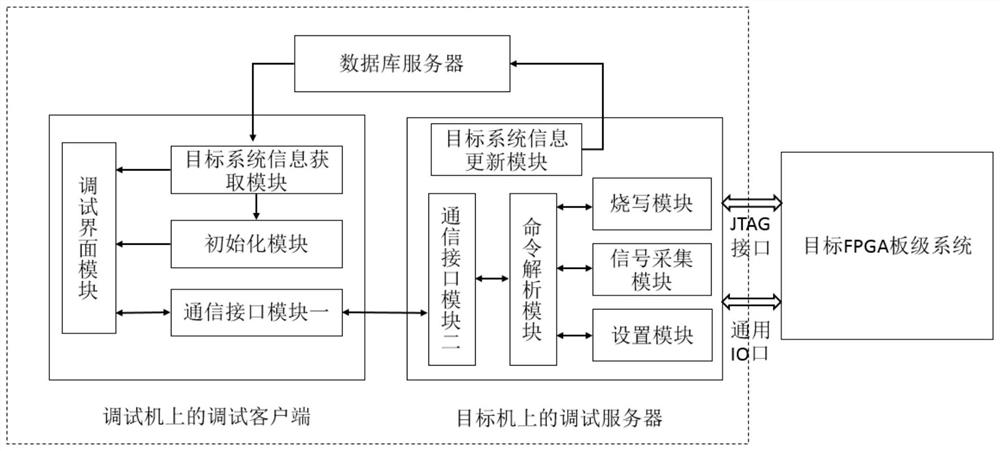
[0051] (2) The debugger clicks the "programming" button on the debugging interface, and the debugging interface module sends the instruction type PROGAMM and the parameter set including file name, file size and file content to form a debugging request packet to the remote communication module one.

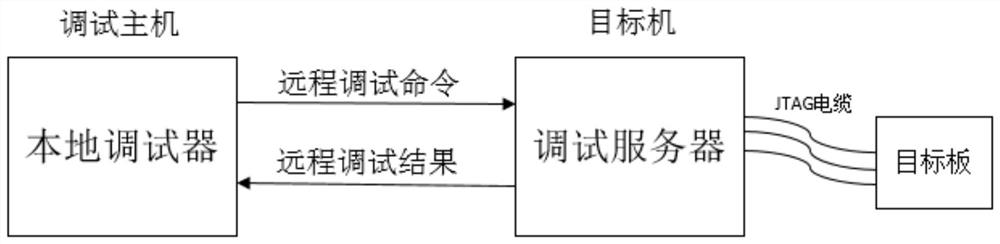
[0052] (3) Once the remote communication module receives the debugging request packet, it sends the debugging request packet to the target computer through the TCP connection and waits for the response packet.

[0053] (4) The second remote communication module receives the debugging request packet, and sends the debugging request packet to the command analysis module.

[0054] (5) The command parsing module par...

Embodiment 2

[0060] Embodiment 2: Immediately collect the signal observed on the target FPGA development board, the steps are as follows:

[0061] (1) The debugger clicks the "trigger immediately" button on the debugging interface, and the debugging interface module forms a debugging request packet composed of an instruction type TRIGGERIMMEDIATELY and an empty parameter set and sends it to the remote communication module one.

[0062] (2) Once the remote communication module receives the debugging request packet, it sends the debugging request packet to the target computer through the TCP connection and waits for the response packet.

[0063] (3) The second remote communication module receives the debugging request packet, and sends the debugging request packet to the command analysis module.

[0064] (4) The command parsing module parses the debugging request packet, parses out that the command type is TRIGGER IMMEDIATELY command, and sends the command to the signal acquisition module. ...


PUM


Abstract

The invention discloses an FPGA remote debugging system and remote debugging method. The system comprises a debugging client running in a debugging host, a debugging server running in a target machine, and a database server used for storing target system information; the remote debugging of an FPGA is completed by the client and the server through a remote debugging communication protocol; the database server stores a target system information table; the debugging client is used for performing user interaction operation, displaying the information, sending a debugging request packet and receiving a debugging response packet; and the debugging server is used for acquiring the target system information, receiving the debugging request packet from the debugging client, performing command analysis on the debugging request packet, forming the debugging response packet and sending the debugging response packet back to the debugging client. By adopting the technical scheme, programming and debugging of hardware codes are carried out on an FPGA board-level system connected to a computer host through the internet; the remote debugging system and method is simple and easy to use; and the development and debugging efficiency can be improved.

Description

technical field [0001] The invention relates to debugging technology in the development process of FPGA (Field Programmable Gate Array, field programmable gate array), in particular to a simple and easy-to-use remote debugging system and debugging method for FPGA board-level systems. Background technique [0002] In modern digital design, FPGA is widely used because of its rich resources and flexible use. With the development of semiconductor technology, FPGA is developing towards system on programmable chip (SOPC), the system is highly integrated, and some key signals only exist inside the chip. More pins of the chip are packaged in a ball grid array (BGA), and the pin connection characteristics cannot be tested by traditional methods. Real-time analysis and debugging of FPGA is an important means to verify the correctness of hardware logic, and it is the last link of system hardware design and implementation. The usual debugging method needs to connect the host computer ...

Claims


Application Information

Patent Timeline
Patent Type & Authority Patents(China)
IPC IPC(8): G06F11/36H04L12/26H04L29/08
CPCG06F11/3664G06F11/3688H04L43/50H04L67/125H04L67/34
Inventor 王韬严磊
Owner PEKING UNIV
Why Eureka
Try Eureka