
Genetic algorithm-based optimization method of multi-piece inclined surface relief tiled grating and inclined surface relief grating waveguide display system

An inclined surface, genetic algorithm technology, applied in the field of inclined surface relief grating waveguide display system, can solve the problem of no grating optimization, etc., and achieve the effect of improving the field of view, good uniformity and high brightness

Inactive Publication Date: 2018-11-02
ZHEJIANG UNIV
View PDF6 Cites 3 Cited by
  • Summary
  • Abstract
  • Description
  • Claims
  • Application Information

AI Technical Summary

Problems solved by technology

Currently there is no specific optimization method to optimize the raster

Method used


Image

  • Genetic algorithm-based optimization method of multi-piece inclined surface relief tiled grating and inclined surface relief grating waveguide display system
  • Genetic algorithm-based optimization method of multi-piece inclined surface relief tiled grating and inclined surface relief grating waveguide display system
  • Genetic algorithm-based optimization method of multi-piece inclined surface relief tiled grating and inclined surface relief grating waveguide display system

Examples


Embodiment 1

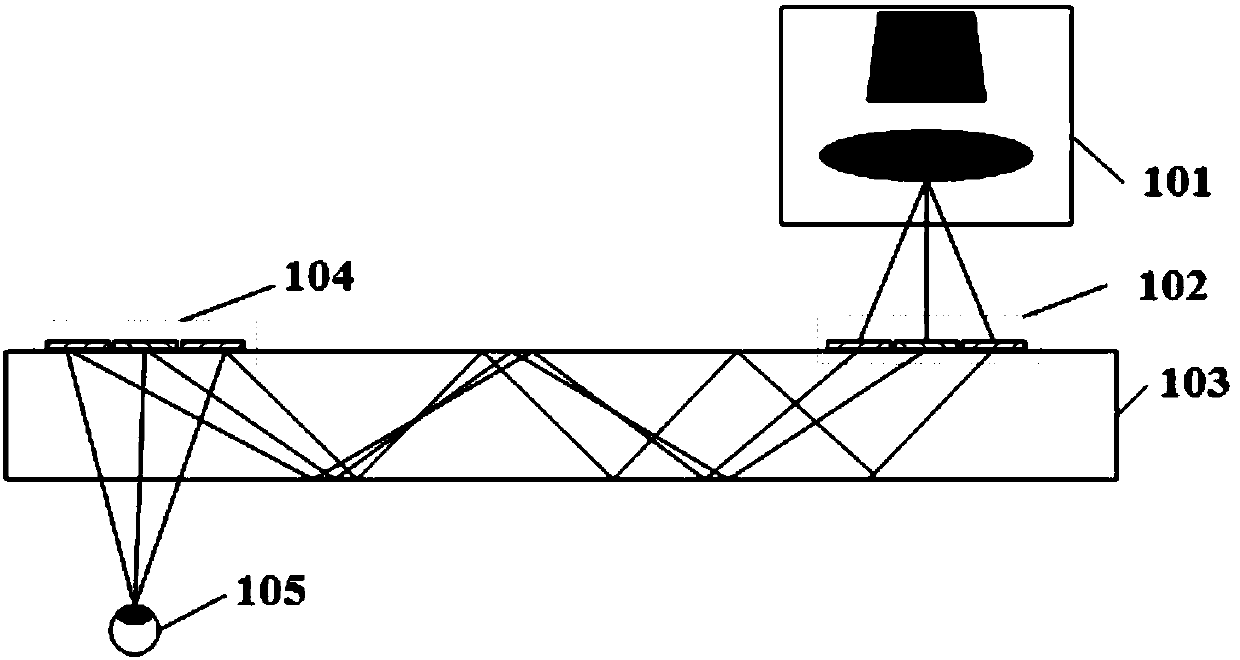
[0052] Such as figure 1 As shown, a tilted surface embossed grating waveguide display system includes: a display module 101, the collimated image emitted by the microdisplay diverges through the lens to the input coupling optical element 102 to be diffracted into the waveguide 103, and the light passes through the total emission along the waveguide forward When the light reaches the output coupling optical element 104 , the light at different angles is coupled out of the waveguide at different positions, and finally converges to the human eye 105 .

[0053] In order to obtain a good display effect, the coupling optical element is required to have a high diffraction efficiency and a wide angular bandwidth, but the general diffraction grating device restricts the two.

[0054] The input-coupling optical element and the output-coupling optical element are three oblique surface embossed gratings, and the three oblique surface embossed gratings are spliced ​​horizontally to expand ...


PUM


Abstract

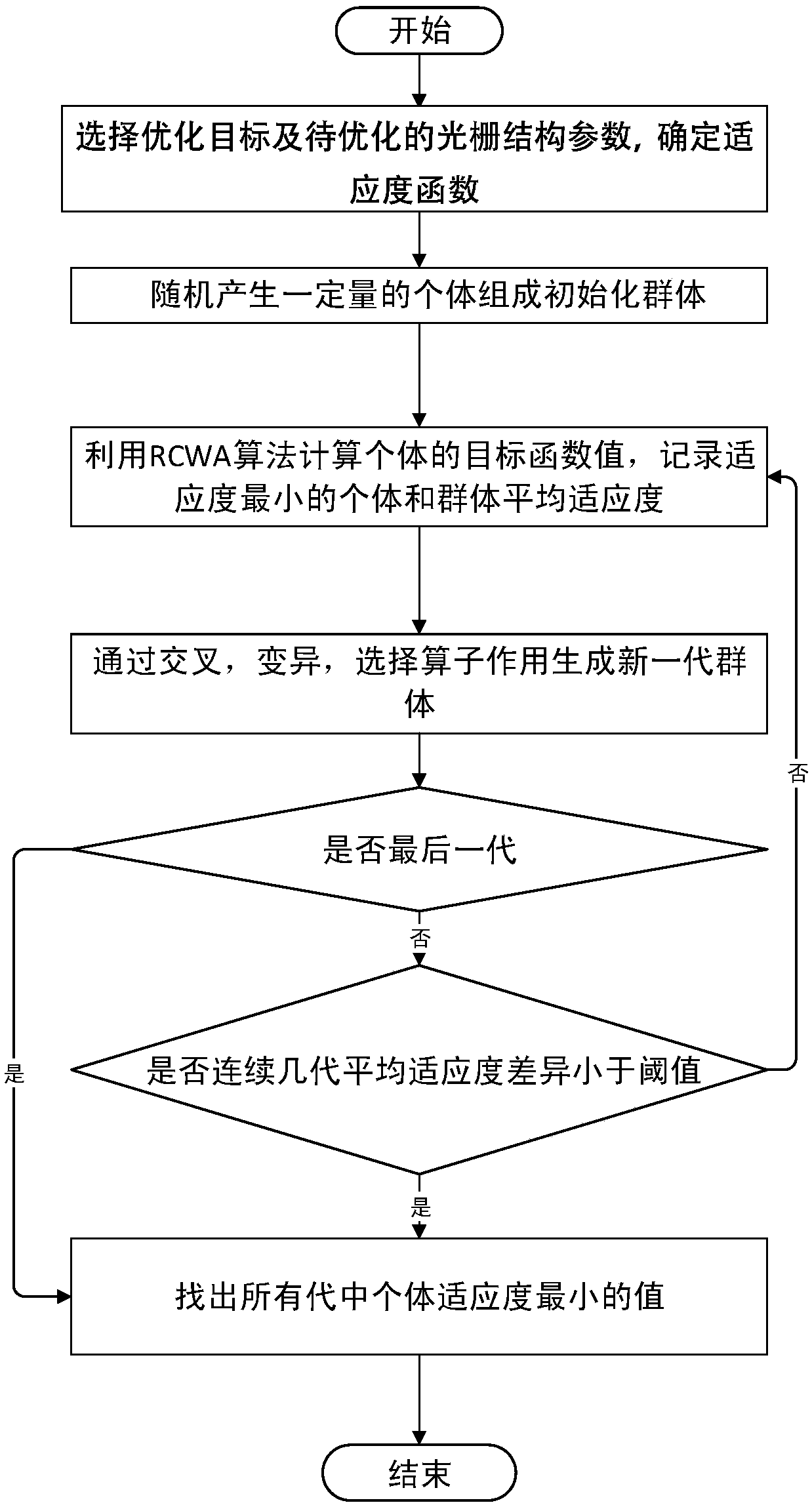
The invention discloses a genetic algorithm-based optimization method of multi-piece inclined surface relief tiled grating and an inclined surface relief grating waveguide display system. The optimization method comprises the following steps of selecting an optimization target and to-be-optimized grating structure parameters, and determining a fitness function of a genetic algorithm; initializinga group, namely, randomly generating multiple groups of grating structure parameters; calculating the fitness of individuals and the average fitness of the group according to the fitness function; generating a next-generation group; judging whether a program is terminated or not, and finding out the grating structure parameters corresponding to the minimum fitness values of the individuals in allgenerations. According to the inclined surface relief grating waveguide display system, three pieces of inclined surface relief gratings are horizontally tiled, and the morphologies of the three pieces of the inclined surface relief gratings are calculated by the optimization method. The inclined surface relief grating waveguide display system has the advantages that while a view field angle is increased, high brightness and good uniformity of the system are ensured.

Description

technical field [0001] The invention belongs to the technical field of diffraction grating waveguide display, and in particular relates to an optimization method of multi-chip inclined surface relief mosaic grating based on genetic algorithm and an inclined surface relief grating waveguide display system. Background technique [0002] Waveguide display technology is currently a mainstream method for realizing augmented reality, which has the characteristics of compact structure and good portability. This display system generally consists of three parts: a display module composed of an image source and an optical collimation system, a waveguide, and a coupling device. The light emitted by the image source passes through the collimation system and then enters the waveguide through the in-coupling grating, undergoes total reflection inside the waveguide, and then enters the human eye through the out-coupling grating. [0003] The patent document with the publication number CN1...

Claims


Application Information

Patent Timeline
IPC IPC(8): G06N3/12G02B27/00
CPCG02B27/0012G06N3/126
Inventor 李海峰赵庆金闻嘉张隽怿刘旭
Owner ZHEJIANG UNIV
Learn More