
Chip structure and packaging method thereof, and electronic equipment

A technology of chip structure and electronic equipment, applied in the direction of circuits, electrical components, electrical solid devices, etc., can solve the problem of uneven force on die DIE11, and achieve the effect of ensuring yield

Pending Publication Date: 2018-11-02
BEIJING BITMAIN TECH LTD
View PDF0 Cites 2 Cited by
  • Summary
  • Abstract
  • Description
  • Claims
  • Application Information

AI Technical Summary

Problems solved by technology

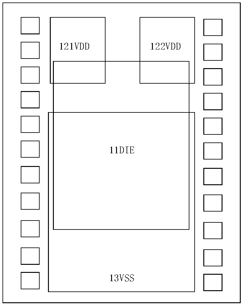
During the installation process of the wafer DIE 11 and the circuit substrate, due to the distance of a certain width between the power input terminal VDD12 and the power supply output terminal VSS13, the force on each part of the wafer DIE 11 is uneven, so that the wafer DIE 11 is in the package. About 10% chip splinter loss occurs during the process

Method used


Image

  • Chip structure and packaging method thereof, and electronic equipment
  • Chip structure and packaging method thereof, and electronic equipment
  • Chip structure and packaging method thereof, and electronic equipment

Examples


Embodiment Construction

[0033] In order to make the purpose, technical solutions and advantages of the present invention clearer, the present invention will be further described in detail below in conjunction with the accompanying drawings. Obviously, the described embodiments are only some of the embodiments of the present invention, rather than all of them. Based on the embodiments of the present invention, all other embodiments obtained by persons of ordinary skill in the art without making creative efforts belong to the protection scope of the present invention.

[0034] In order to ensure that the wafer DIE is evenly stressed during the packaging process, without chip chip loss, and to ensure the yield rate of chip production, the embodiment of the present invention provides a chip structure, such as figure 2 and image 3 shown. figure 2 Shown is a schematic diagram of the mapping of the chip element and the power supply on the metal layer provided in the first embodiment of the present inven...


PUM


Abstract

The embodiment of the invention discloses a chip structure and a packaging method thereof, and electronic equipment. the chip comprises a wafer (DIE) and a circuit substrate, wherein the circuit substrate comprises a first bonding pad (VSS), a second bonding pad (VDDS) and a third bonding pad (VDDM); the wafer (DIE) is arranged on the first bonding pad (VSS), the mapping plane of the wafer (DIE) on the first bonding pad (VSS) is within the frame of the first bonding pad (VSS). Compared with the prior art, in the embodiment of the invention, the wafer (DIE) is arranged on the first bonding pad(VSS), the mapping plane of the wafer (DIE) on the first bonding pad (VSS) is within the frame of the first bonding pad (VSS), the wafer (DIE) does not stretch across two or more pads, the wafer (DIE)is prevented from being subjected to non-uniform stress during a packaging process, and thus loss caused by cracking of the chip is avoided, and the production yield of the chip is ensured.

Description

technical field [0001] The invention relates to the technical field of chip design, in particular to a chip structure, a packaging method thereof, and electronic equipment. Background technique [0002] Usually, as Figure 1a and 1b As shown, it is the traditional internal structure of the chip, including the wafer DIE 11 and the copper pillar BUMP15 on the circuit substrate, the power input terminal VDD12, the power output terminal VSS13 and the solder mask green oil SM14. When power is supplied to the wafer DIE 11 through the power input terminal VDD12 and the power output terminal VSS13, in order to keep the voltages of each core on the DIE equal, it is necessary to reduce the IR drop (IR Drop) of the power input terminal VDD12 and the power output terminal VSS13 needs, it is necessary to reduce the transmission resistance R. According to the formula R=ρL / S (where R represents the resistance value, ρ represents the resistivity, L represents the distance, and S represent...

Claims


Application Information

Patent Timeline
Patent Type & Authority Applications(China)
IPC IPC(8): H01L23/498H01L21/48
CPCH01L23/49838H01L21/4846H01L2224/16225H01L2224/16235
Inventor 易泓历
Owner BEIJING BITMAIN TECH LTD
Learn More