Rotating power-assisted mechanism and lifting table applying same

A technology of a power assist mechanism and a lifting table, which is applied in the field of lifting tables, can solve the problems of heavy table board, troublesome installation, and different operations, and achieves the effects of simple structure and low manufacturing cost.

Pending Publication Date: 2018-11-06
ZHEJIANG LEGE INTELLIGENT DRIVE TECH CO LTD
View PDF24 Cites 25 Cited by
  • Summary
  • Abstract
  • Description
  • Claims
  • Application Information

AI Technical Summary

Problems solved by technology

The height adjustment of the lift table is generally a manual adjustment. As the structure of the lift table in the prior art includes a table board, a base, and liftable table legs, and a crossbeam connecting the table legs, the crossbeam is provided with a rotating shaft. The rotation drives the table legs to rise and fall; the rotation of the rotating shaft is driven by the rotation of the crank; because there are many items placed on the desk and the weight of the table is heavy, the lifting table is generally equipped with a booster mechanism to provide the table. The auxiliary lifting force of rising, so that the operator is more labor-saving when shaking the handle; the assisting mechanism is generally provided with a gas spring to provide the auxiliary lifting force of the table. Connection, that is, one end of the gas spring is connected to the base, and the other end of the gas spring is connected to the table leg; when installing the lifting table with this structure, the customer is troublesome to install, and the operation is very difficult; in addition, the exposed gas spring will cause safety problems. Hidden danger; moreover, adopt two gas springs to provide boost, make the manufacturing cost of lift table increase

Method used


Image

  • Rotating power-assisted mechanism and lifting table applying same
  • Rotating power-assisted mechanism and lifting table applying same
  • Rotating power-assisted mechanism and lifting table applying same

Examples


Embodiment Construction

[0029] The present invention will be described in further detail below in conjunction with the accompanying drawings and specific embodiments.

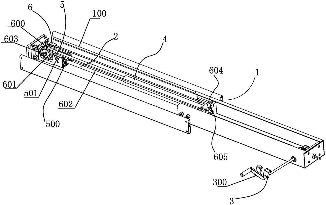
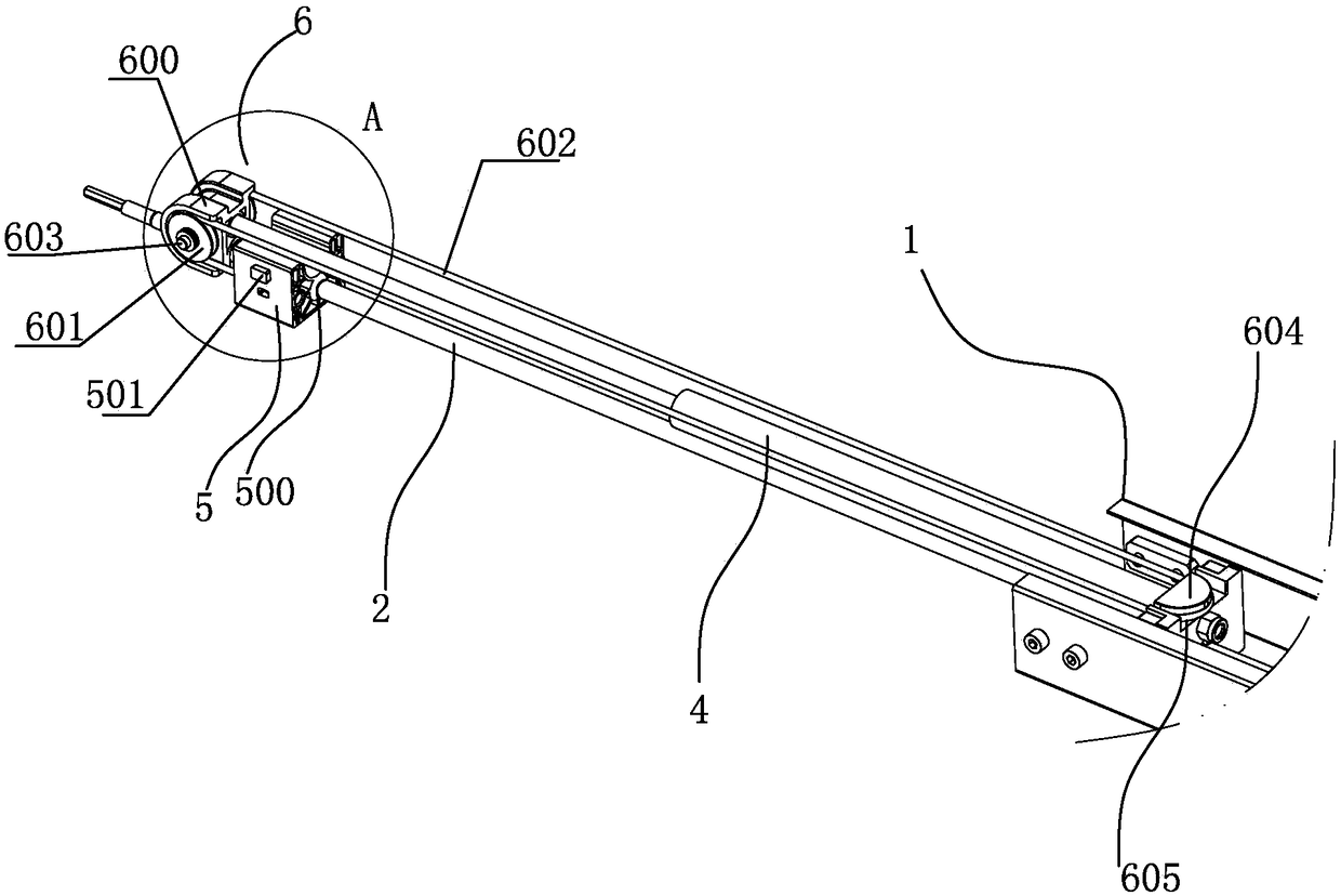
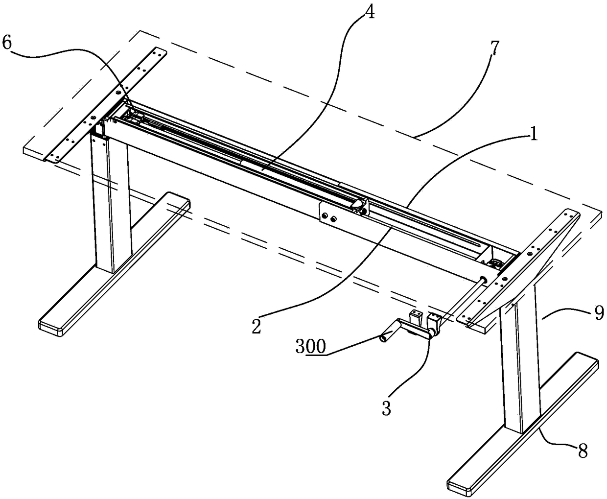
[0030] Such as figure 1 , figure 2 and Figure 5 shown;

[0031] The rotation assisting mechanism of the present invention comprises a transmission shaft 2 arranged on a support member 1 and a drive device 3 for driving the transmission shaft 2 to rotate, and a slide block 5 is screwed on the transmission shaft 2; on the support member 1 An energy storage element 4 whose axis is parallel to the axis of the transmission shaft 2 is provided, one end of the energy storage element 4 is connected to the support member 1, and the other end of the energy storage element 4 is connected to the slider 5, and the energy storage element 4 It is used to apply thrust to the slider 5, and provide power assistance for the rotation of the transmission shaft 2 through the slider 5. When the rotation assist mechanism is working, the driving device ...


PUM


Abstract

The invention discloses a rotating power-assisted mechanism and a lifting table applying the same. The rotating power-assisted mechanism comprises a transmission shaft arranged on a supporting memberand a driving device driving the transmission shaft to rotate, a slider is connected on the transmission shaft in a threaded manner, an energy storage element with axis parallel to that of the transmission shaft is arranged on the supporting member, the first end of the energy storage element is connected with the supporting member while the second end of the same is connected with the slider, andthe energy storage element is used for applying thrust on the slider and providing power assistance for rotating of the transmission shaft through the slider. The rotating power-assisted mechanism and the lifting table are low in manufacturing cost, simple in structure and high in safety.

Description

technical field [0001] The invention relates to the technical field of lifting tables, in particular to a rotating power-assisted mechanism and a lifting table for its application. Background technique [0002] An adjustable desk is a height-adjustable desk that can be adjusted according to a person's height, sitting posture, and standing posture. The height adjustment of the lift table is generally a manual adjustment. As the structure of the lift table in the prior art includes a table board, a base, and liftable table legs, and a crossbeam connecting the table legs, the crossbeam is provided with a rotating shaft. The rotation drives the table legs to rise and fall; the rotation of the rotating shaft is driven by the rotation of the crank; because there are many items placed on the desk and the weight of the table is heavy, the lifting table is generally equipped with a booster mechanism to provide the table. The auxiliary lifting force of rising, so that the operator is...

Claims


Application Information

Patent Timeline
Patent Type & Authority Applications(China)
IPC IPC(8): A47B9/12A47B13/02
CPCA47B9/12A47B13/02A47B2200/0052
Inventor 项乐宏蒋领辉封迪庆
Owner ZHEJIANG LEGE INTELLIGENT DRIVE TECH CO LTD
Why Eureka
Try Eureka