
Continuous machining punching device for large-batch nut production

A punching device and large-scale technology, applied in the field of nut production, can solve the problems of inability to meet the processing needs of large-scale nuts, poor practicability, poor continuity, etc., and achieve the effect of novel design, strong practicability and reasonable structure

Inactive Publication Date: 2018-11-06
WUHAN MATENG TECH DEV
View PDF9 Cites 2 Cited by
  • Summary
  • Abstract
  • Description
  • Claims
  • Application Information

AI Technical Summary

Problems solved by technology

[0004] In the current processing of common nuts, it is usually divided into two processing procedures. First, holes are drilled on the pre-processed screw blocks, and the screw blocks after drilling are then tapped to form nuts. During the nut drilling process, the efficiency is relatively low. Generally, one hydraulic punching is only carried out for one station. The continuity is poor, which cannot meet the needs of large-scale nut processing, and the practicability is not strong.

Method used


Image

  • Continuous machining punching device for large-batch nut production
  • Continuous machining punching device for large-batch nut production
  • Continuous machining punching device for large-batch nut production

Examples


Embodiment Construction

[0021] It should be noted that, in the case of no conflict, the embodiments of the present invention and the features in the embodiments can be combined with each other.

[0022] In describing the present invention, it should be understood that the terms "center", "longitudinal", "transverse", "upper", "lower", "front", "rear", "left", "right", " The orientations or positional relationships indicated by "vertical", "horizontal", "top", "bottom", "inner" and "outer" are based on the orientations or positional relationships shown in the drawings, and are only for the convenience of describing the present invention and The description is simplified, rather than indicating or implying that the device or screw referred to must have a specific orientation, be constructed and operate in a specific orientation, and thus should not be construed as limiting the invention. In addition, the terms "first", "second", etc. are used for descriptive purposes only, and should not be understood ...


PUM


Abstract

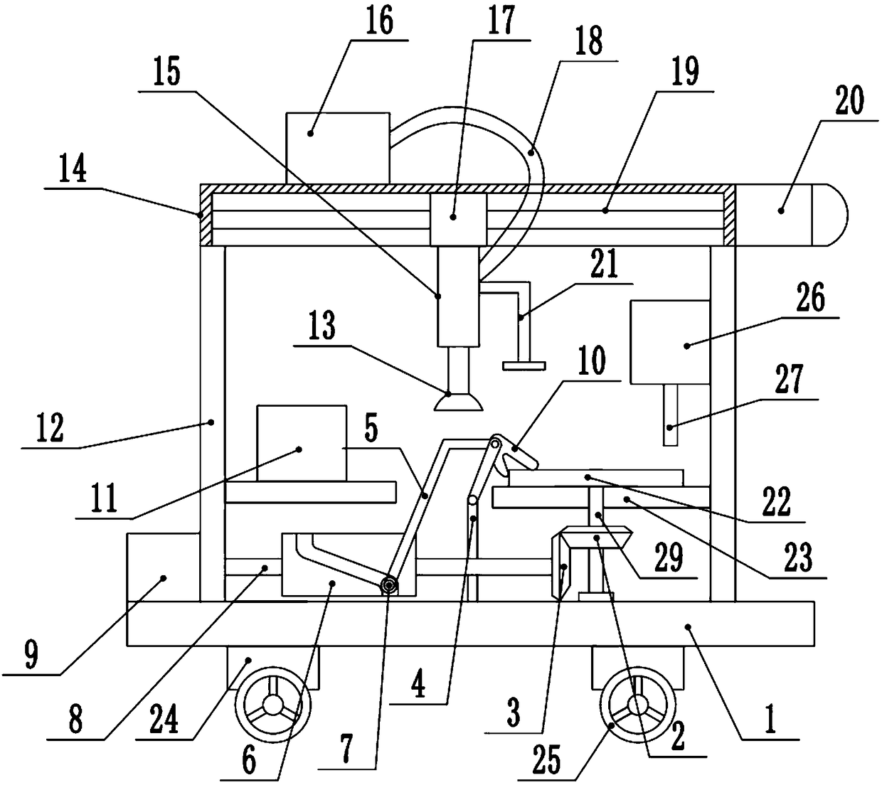
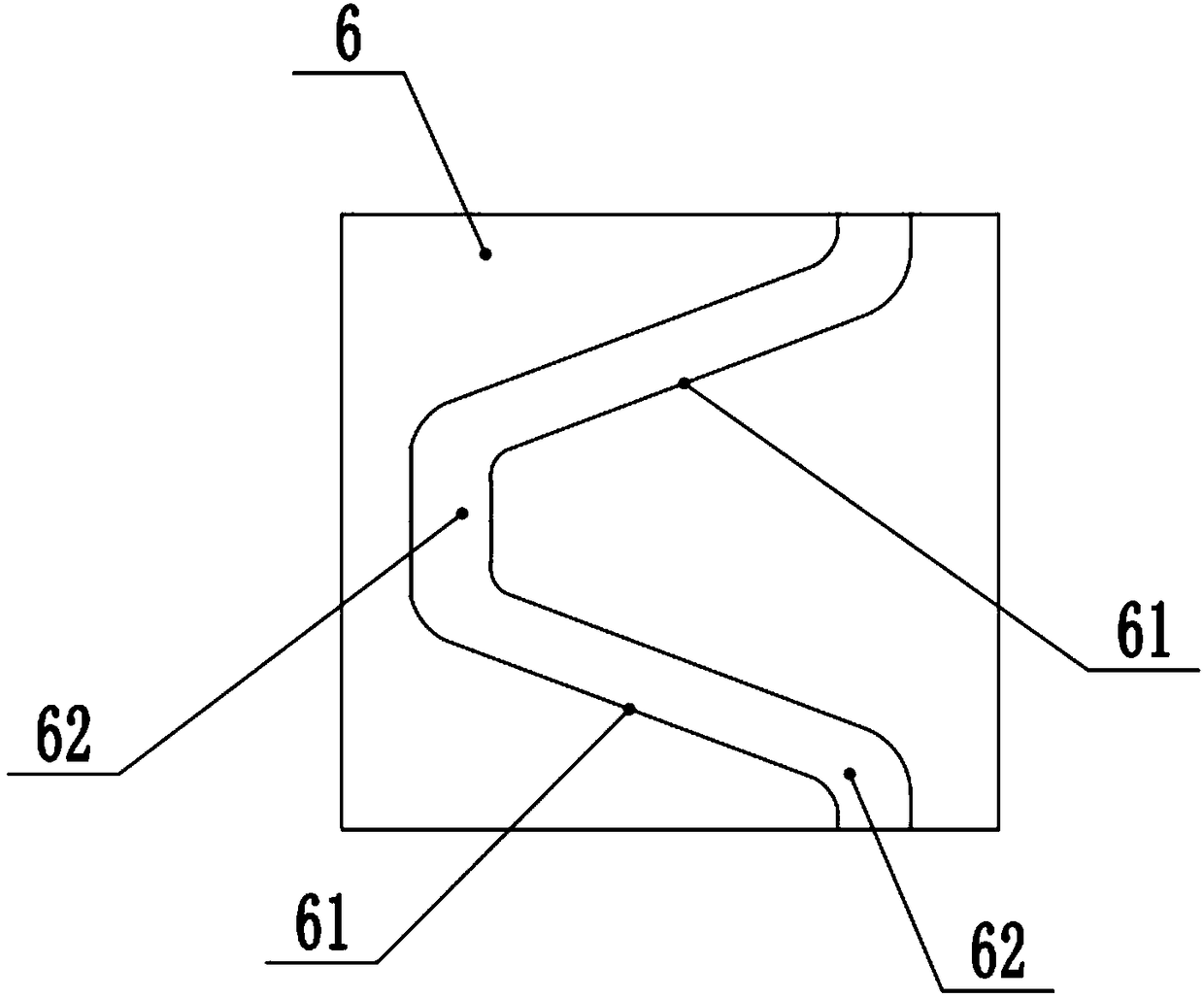
The invention discloses a continuous machining punching device for large-batch nut production. The continuous machining punching device comprises a base. The two sides of the upper end of the base areconnected with supporting frames. The upper ends of the supporting frames are connected with a sliding sleeve. A sliding block is arranged in the sliding sleeve. The middle portion of the sliding block is provided with a rotation screw. A drive motor is fixed to the left side of the upper end of the base. The right end of the drive motor is connected with a drive shaft. The right end of the driveshaft is connected with a roller. An inclined sliding way is arranged at the middle portion of the outer side of the roller. A running pulley is arranged at the middle portion of the inclined slidingway and the middle portions of straight sliding ways, the upper end of the running pulley is connected with a pull rod, the right end of the pull rod is connected with a clamping block, and the rightend of the roller is connected with a drive gear. The upper end of the drive gear is connected with a transmission gear. A rotation shaft is connected to the middle portion of the transmission gear.The upper end of the rotation shaft penetrates the workbench and is connected with a machining die. Through the continuous machining punching device, rotary punching of a nut block in the machining die is achieved, the situation that one punching hydraulic cylinder can only punch one station is avoided, the continuous punching requirement is met, the large-batch nut machining requirement is met, and practicability is high.

Description

technical field [0001] The invention relates to the technical field of nut production, in particular to a continuous processing and drilling device for mass production of nuts. Background technique [0002] A nut is a nut, a part that is screwed together with a bolt or a screw for fastening. A screw block that must be used in all manufacturing machinery is divided into carbon steel, stainless steel, and non-ferrous metals (such as copper) according to different materials. Nuts are parts that tightly connect mechanical equipment. Nuts and bolts of the same specification can be connected together through internal threads. For example, M4-P0.7 nuts can only be connected with M4-P0.7 series bolts. (In the nut, M4 means that the inner diameter of the nut is about 4mm, and 0.7 means that the distance between two thread teeth is 0.7mm); the same is true for American products, for example, a 1 / 4-20 nut can only be used with a 1 / 4- 20 screw matching (1 / 4 finger nut inner diameter is...

Claims


Application Information

Patent Timeline
Patent Type & Authority Applications(China)
IPC IPC(8): B21D28/36
CPCB21D28/36
Inventor 陈德高
Owner WUHAN MATENG TECH DEV
Learn More