Polishing device for steel pipe machining

A technology for steel pipes and grinding wheels, which is applied in the direction of grinding drive devices, grinding/polishing safety devices, metal processing equipment, etc., can solve the problems of physical consumption, operator injury, and reducing the speed of steel pipe grinding, so as to reduce the vibration amplitude, Improve the service life and facilitate the effect of grinding

Inactive Publication Date: 2018-11-06
天津亚源泰钢管有限公司
View PDF5 Cites 4 Cited by
  • Summary
  • Abstract
  • Description
  • Claims
  • Application Information

AI Technical Summary

Problems solved by technology

[0002] The machining workshop is the basic production unit of the machinery manufacturing plant. In the workshop, when the steel pipe needs to be polished, the existing method is to manually wipe the surface of the steel pipe with sandpaper, so as to make the surface of the steel pipe clean and derust the steel pipe. However, At the same time, due to the friction between the sandpaper and the steel pipe, a large amount of heat will be generated, which will also cause damage to the hands of the operator, causing unnecessary damage. Some mechanical tools such as grinding wheels are used for grinding, and the steel pipe needs to be manually rotated back and forth. Adjust the position of the grinding wheel back and forth, so it consumes more energy, and also reduces the grinding speed of the steel pipe
[0003] A Chinese patent discloses a comprehensive steel pipe rapid grinding device for workshop processing (authorized announcement number CN107695806A). This patented technology can realize steel pipe grinding and reduce labor intensity, but there is no waste collection. The structure of this device is complicated, and the steel pipe How much vibration does the grinding process

Method used


Image

  • Polishing device for steel pipe machining
  • Polishing device for steel pipe machining
  • Polishing device for steel pipe machining

Examples


Embodiment Construction

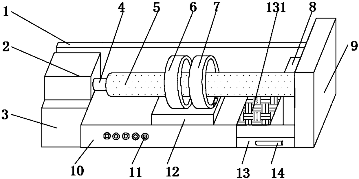
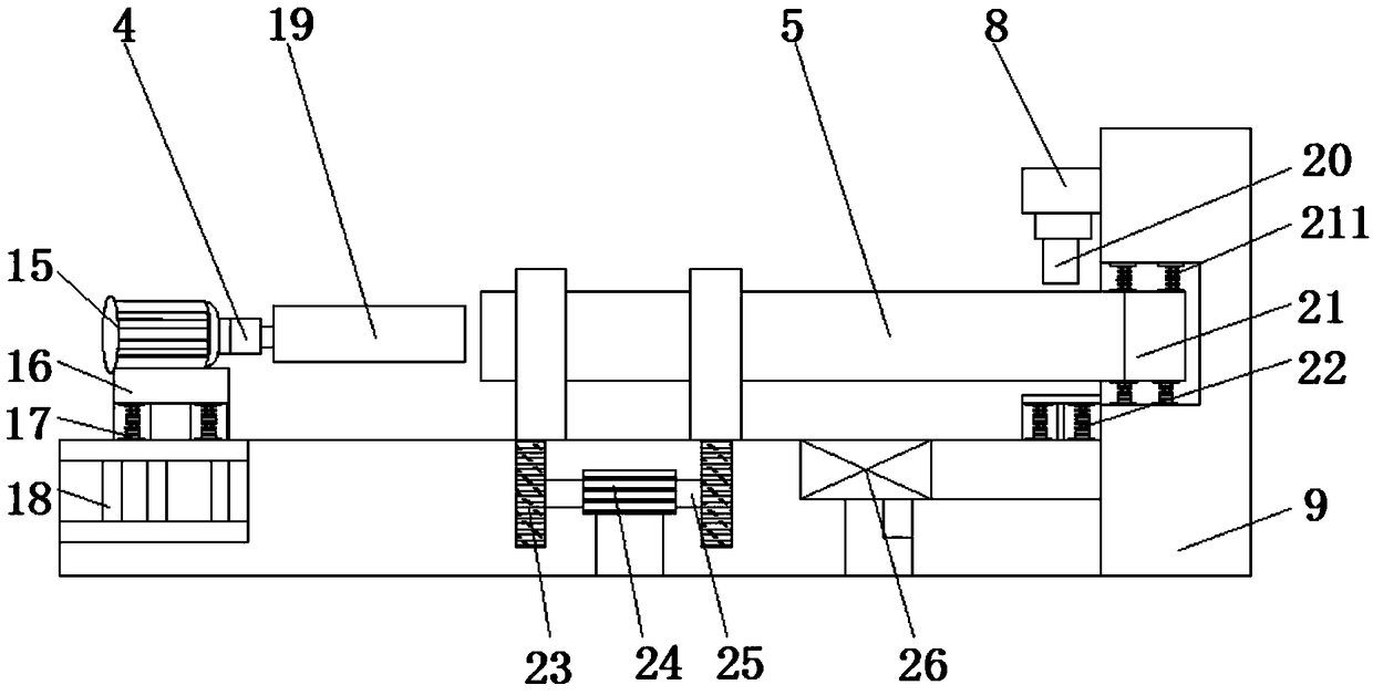
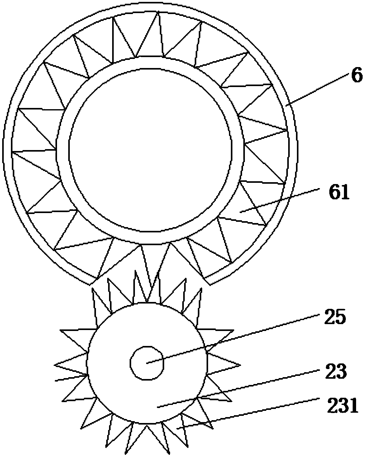
[0022] see Figure 1~3 , in an embodiment of the present invention, a grinding device for steel pipe processing includes a base 10, the side surface of the base 10 is fixedly provided with a motor base 3, and the upper surface of the motor base 3 is fixedly installed with a first motor box 2, the base 10 The rear surface of the base 10 is fixedly provided with a baffle plate 1, the other side surface of the base 10 is fixedly provided with a support seat 9, the front surface of the base 10 is embedded with a control switch 11, and the inner top of the first motor box 2 is fixedly installed with a motor 15 One side of the motor 15 is fixedly equipped with an electric telescopic rod 4, and one end of the electric telescopic rod 4 is fixedly sleeved with a third grinding wheel 19, and the middle part of the support seat 9 is fixedly provided with a groove 21, and one side of the support seat 9 A support plate 8 is fixedly installed near the upper position of the groove 21, a tele...


PUM


Abstract

The invention discloses a polishing device for steel pipe machining. The polishing device for steel pipe machining comprises a base, a motor pedestal is fixedly arranged on the lateral surface of thebase, and a first motor box is fixedly installed on the upper surface of the motor pedestal. Due to the arrangement of a double-shaft motor, gears, a large gear, a first polishing wheel and a second polishing wheel, on the one hand, steel pipes are conveniently supported, and on the other hand, the outer walls of the steel pipes are conveniently polished and treated; due to the arrangement of a groove, a telescopic rod, second springs and third springs, the steel pipes with different pipe diameters are conveniently fixed, and the steel pipes with different sizes are conveniently polished and treated; due to the arrangement of first springs, a first supporting plate, supporting posts, an electric telescopic rod and a third polishing wheel, stable supporting of the motor is facilitated, andmeanwhile the vibration amplitude generated when the motor works is reduced; and due to the arrangement of a through hole, an exhaust fan and a waste scrap drawer, waste scraps generated in the steelpipe polishing process are conveniently collected and treated.

Description

technical field [0001] The invention relates to a steel pipe processing device, in particular to a grinding device for steel pipe processing. Background technique [0002] The machining workshop is the basic production unit of the machinery manufacturing plant. In the workshop, when the steel pipe needs to be polished, the existing method is to manually wipe the surface of the steel pipe with sandpaper, so as to make the surface of the steel pipe clean and derust the steel pipe. However, At the same time, due to the friction between the sandpaper and the steel pipe, a large amount of heat will be generated, which will also cause damage to the hands of the operator, causing unnecessary damage. Some mechanical tools such as grinding wheels are used for grinding, and the steel pipe needs to be manually rotated back and forth. The position of the grinding wheel is adjusted back and forth, so it consumes more physical strength, and also reduces the grinding speed of the steel pip...

Claims


Application Information

Patent Timeline
Patent Type & Authority Applications(China)
IPC IPC(8): B24B5/12B24B27/033B24B55/06B24B41/00B24B41/06B24B47/12
CPCB24B5/12B24B27/033B24B41/007B24B41/067B24B47/12B24B55/06
Inventor 刘广学刘怀民
Owner 天津亚源泰钢管有限公司
Why Eureka
Try Eureka