
3D printing method for hyperbaric oxygen chamber

A hyperbaric oxygen chamber and 3D printing technology, applied in the direction of improving energy efficiency, improving process efficiency, and additive manufacturing, etc., can solve problems such as increased manufacturing costs, transportation difficulties, and increased inspection difficulties, so as to increase adaptability and ensure structural strength Effect

Active Publication Date: 2018-11-06
铜仁市人民医院
View PDF4 Cites 2 Cited by
  • Summary
  • Abstract
  • Description
  • Claims
  • Application Information

AI Technical Summary

Problems solved by technology

There are many problems in this structure: first, the use of steel plates makes the hyperbaric oxygen chamber heavy and difficult to transport; second, because the working pressure of the hyperbaric oxygen chamber is about 3Kg, the requirements for welding quality are relatively high, and inspection and flaw detection It is very strict, and the oversized cabin also increases the difficulty of inspection and increases the manufacturing cost; third, the cylindrical cabin is not conducive to the patient's movement, affects the patient's adaptability to the cabin, and may also reduce the space of the cabin. Utilization rate; Fourth, because the cabin body is not convenient for transportation, it is basically manufactured at the manufacturer, and it cannot be changed on site. The adaptability to the site is poor, and a little carelessness may lead to failure to install and use
[0003] Due to the existence of the above problems, the use level of the hyperbaric oxygen chamber is restricted.

Method used


Image

  • 3D printing method for hyperbaric oxygen chamber
  • 3D printing method for hyperbaric oxygen chamber
  • 3D printing method for hyperbaric oxygen chamber

Examples


Embodiment Construction

[0054]In order to make the purpose, technical solutions and advantages of the embodiments of the present invention clearer, the technical solutions in the embodiments of the present invention will be clearly and completely described below in conjunction with the drawings in the embodiments of the present invention. Obviously, the described embodiments It is a part of embodiments of the present invention, but not all embodiments. The components of the embodiments of the invention generally described and illustrated in the drawings herein may be arranged and designed in a variety of different configurations.

[0055] Accordingly, the following detailed description of the embodiments of the invention provided in the accompanying drawings is not intended to limit the scope of the claimed invention, but merely represents selected embodiments of the invention. Based on the embodiments of the present invention, all other embodiments obtained by persons of ordinary skill in the art wi...


PUM


Abstract

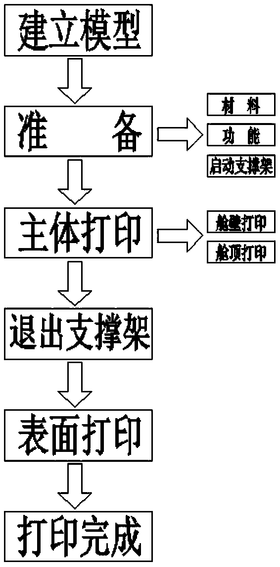
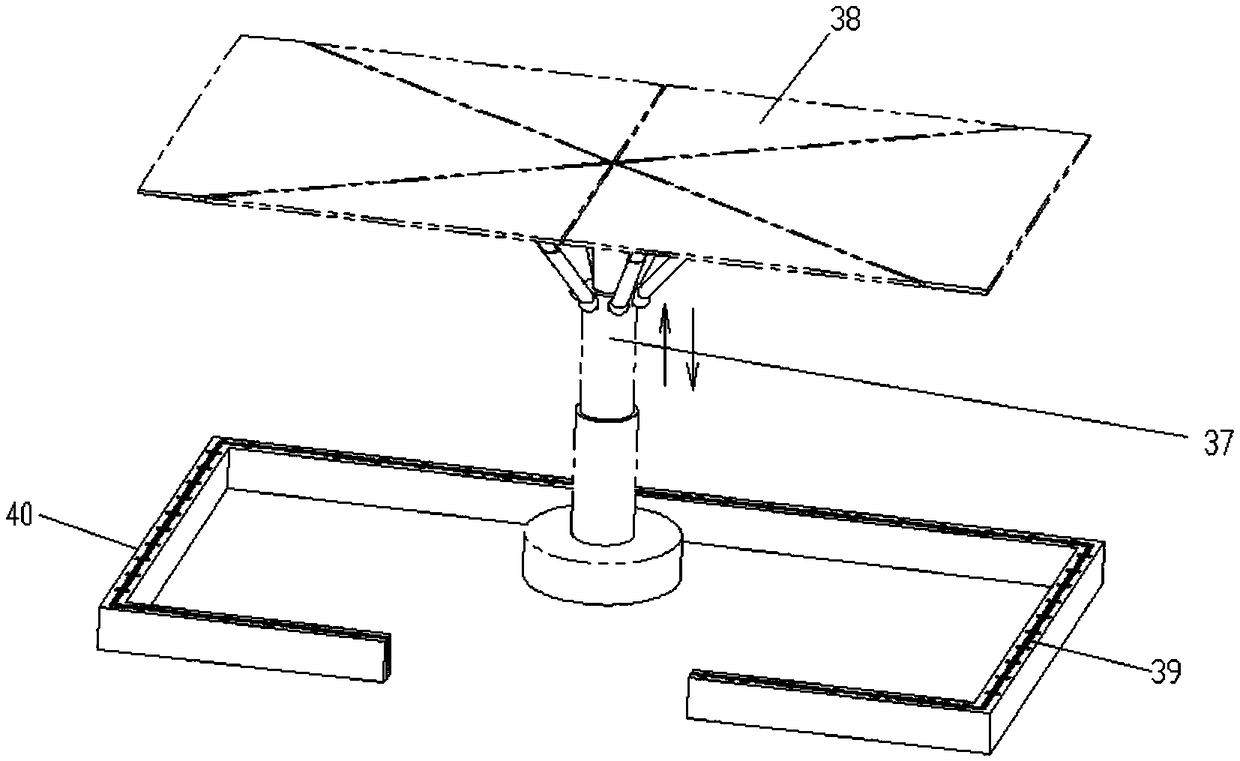
The invention relates to a 3D printing method for a hyperbaric oxygen chamber and belongs to the technical field of hyperbaric oxygen chamber manufacturing. The 3D printing method comprises the following steps: 1) establishing a model: determining the size and the contour of the hyperbaric oxygen chamber by combining the size of a site and a surrounding environment according to actual demands to establish a mathematical model of the hyperbaric oxygen chamber, and importing the mathematical model into an analyzing processing system of hyperbaric oxygen chamber 3D printing equipment to be analyzed to obtain a printing program; 2) preparation: debugging the equipment to confirm that functional parts move normally; examining the stock of a print material; and starting a roof supporting rack tolift the supporting surface of the roof supporting rack to the top of the chamber and smearing a release agent to the surface of the chamber; 3) main body printing; and 4) surface printing. The hyperbaric oxygen chamber can be directly printed in a service site by means of the 3D printing method and needs not to be produced and manufactured in a professional manufacturer. The size and shape of the hyperbaric oxygen chamber can be adjusted dependent on sites, so that the adaptive capacity of the hyperbaric oxygen chamber to the site and the adaptive capacity of a patient to the hyperbaric oxygen chamber are improved greatly.

Description

technical field [0001] The invention relates to the technical field of hyperbaric oxygen chamber manufacturing, in particular to a 3D printing method for a hyperbaric oxygen chamber. Background technique [0002] The hyperbaric oxygen chamber for treatment is basically rolled into a cylinder with steel plates, and then welded at the joints of the end and the ends and the covers at both ends to make it a closed cylinder. There are many problems in this structure: firstly, due to the use of steel plate material, the hyperbaric oxygen chamber is heavy and difficult to transport; secondly, because the working pressure of the hyperbaric oxygen chamber is about 3Kg, the requirements for welding quality are relatively high, and inspection and flaw detection It is very strict, and the oversized cabin also increases the difficulty of inspection and increases the manufacturing cost; third, the cylindrical cabin is not conducive to the patient's movement, affects the patient's adaptabi...

Claims


Application Information

Patent Timeline
IPC IPC(8): B28B1/00B22F3/00B33Y10/00B33Y30/00B33Y70/00B22F10/10B22F12/53
CPCB28B1/001B33Y10/00B33Y30/00B33Y70/00B22F10/00B22F10/10B22F12/22B22F12/55B22F12/53Y02P10/25
Inventor 李宁黄丽娟杨再琴冉红叶陈容敖新珍张涛李劲松
Owner 铜仁市人民医院
Learn More